Nissan Rogue Service Manual: Front wiper arm
Exploded View
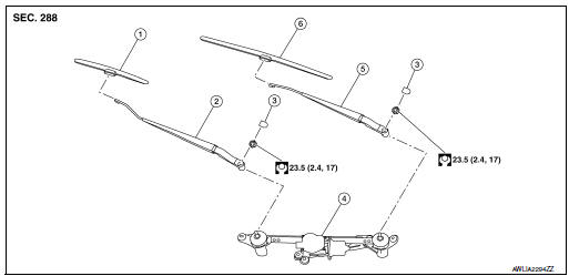
- Front wiper blade (RH)
- Front wiper arm (RH)
- Front wiper arm cover
- Front wiper drive assembly
- Front wiper arm (LH)
- Front wiper blade (LH)
Removal and Installation
REMOVAL
- Move front wiper into the service position by turning the ignition switch ON, then quickly push the wiper washer switch to the mist position two times within 0.5 seconds.
- Turn the ignition switch OFF.
- Remove front wiper arm covers.
- Remove nuts and remove front wiper arms.
INSTALLATION
- Clean wiper arm mount as shown in the figure to prevent nuts from being loosened.
- Move front wiper into the service position by turning the ignition switch ON, then quickly push the wiper washer switch to the mist position two times within 0.5 seconds.
- Turn the ignition switch OFF.
- Adjust front wiper blade position. Refer to WW-64, "Adjustment".
- Install front wiper arm by tightening the nuts.
- Install front wiper arm covers.
- Check that the front wiper blades stop at the specified position.
Adjustment
- Wiper blade (RH)
- Front fender (RH)
- Windshield glass
- Cowl top cover
- Wiper blade (LH)
- 34.9 ┬▒ 7.5 mm (1.4 ┬▒ 0.3 in)
- 38.2 ┬▒ 7.5 mm (1.5 ┬▒ 0.3 in)
 Front washer nozzle and tube
Exploded View
Cowl top cover
Front washer tube
Front washer nozzle (LH)
Front washer nozzle (RH)
Pawl
Clip
Exploded View
Cowl top cover
Front washer tube
...
 Front wiper blade
Exploded View
Wiper blade (RH)
Wiper arm (RH)
Wiper arm cover
Front wiper drive assembly
Wiper arm (LH)
Wiper blade (LH)
Removal and Installation
REMOVAL
Move front ...
Other materials:
Wheel and tire
Adjustment
BALANCING WHEELS (ADHESIVE WEIGHT TYPE)
Preparation Before Adjustment
Remove inner and outer balance weights from the wheel. Using releasing agent,
remove double-faced adhesive
tape from the wheel and tire.
CAUTION:
Be careful not to scratch the wheel and tire during remo ...
How to use the [ ] button
For additional information, refer to the separate
Navigation System OwnerтАЩs Manual regarding
the тАЬSiriusXM┬о Travel LinkтАЭ, and тАЬTrafficтАЭ features.
For additional information, refer to тАЬNissan-
ConnectSM with Mobile AppsтАЭ in this section
regarding тАЬMy AppsтАЭ key.
For ad ...
Mixture ratio self-learning value clear
Description
This describes how to erase the mixture ratio self-learning value. For the
actual procedure, follow the instructions
in тАЬDiagnosis ProcedureтАЭ.
Work Procedure
1.START
With CONSULT
Start engine and warm it up to normal operating temperature.
Select тАЬSELF-LEA ...
