Nissan Rogue Service Manual: Both doors mirror defogger donŌĆÖt operate but rear window defogger operates
Diagnosis Procedure
Regarding Wiring Diagram information, refer to DEF-12, "Wiring Diagram".
1. CHECK DOOR MIRROR DEFOGGER FUSE
Check if the following fuse in fuse block (J/B) is blown.

Is the inspection result normal? YES >> GO TO 2.
NO >> Replace the blown fuse after repairing the affected circuit.
2. CHECK DOOR MIRROR DEFOGGER POWER SUPPLY CIRCUIT
- Turn ignition switch ON.
- Check voltage between fuse block (J/B) harness connector and ground.
Is the inspection result normal? YES >> GO TO 3.
NO >> Replace fuse block (J/B).
3. CHECK BOTH DOOR MIRROR DEFOGGER
- Check door mirror LH. Refer to DEF-28, "Component Function Check".
- Check door mirror RH. Refer to DEF-30, "Component Function Check".
Is the inspection result normal? YES >> Check intermittent incident. Refer to GI-41, "Intermittent Incident".
NO >> Repair or replace the malfunctioning parts.
 Rear window defogger does not operate but both of door mirror defogger
operate
Rear window defogger does not operate but both of door mirror defogger
operate
Diagnosis Procedure
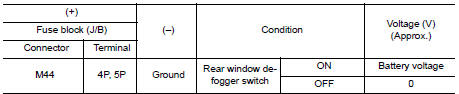
1. CHECK REAR WINDOW DEFOGGER POWER SUPPLY AND GROUND CIRCUIT
Check rear window defogger power supply and ground circuit.
Refer to DEF-26, "Component Function Check" ...
 Driver side door mirror defogger does not operate
Diagnosis Procedure
1. CHECK DOOR MIRROR DEFOGGER LH
Check door mirror defogger LH.
Refer to DEF-28, "Component Function Check".
Is the inspection result normal?
YES >> Refer ...
Other materials:
Oil pan and oil strainer
Exploded View
Oil pan, upper
Oil filter
Front cover
O-ring
Oil strainer
Oil pan, lower
Washer
Drain plug
O-ring
Oil level gauge guide
Oil level gauge
Rear cover plate
To Oil pan, lower
Removal and In ...
Fuel-filler door
Opener operation
Opener operation
The fuel-filler lid release is located below the
instrument panel. To open the fuel-filler lid, pull
the release. To lock, close the fuel-filler lid securely.
Fuel-filler cap
WARNING
Gasoline is extremely flammable and
highly explosive ...
P0172 fuel injection system function
DTC Description
DTC DETECTION LOGIC
With the Air/Fuel Mixture Ratio Self-Learning Control, the actual mixture
ratio can be brought closely to the
theoretical mixture ratio based on the mixture ratio feedback signal from the
A/F sensors 1. The ECM calculates
the necessary compensation to corr ...
