Nissan Rogue Service Manual: Wiring diagram
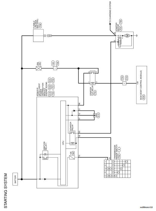
STARTING SYSTEM
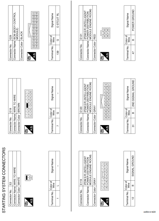
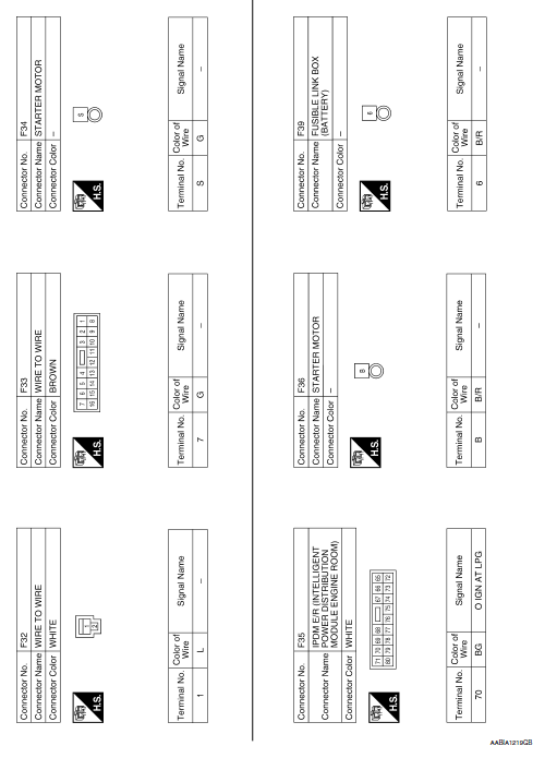
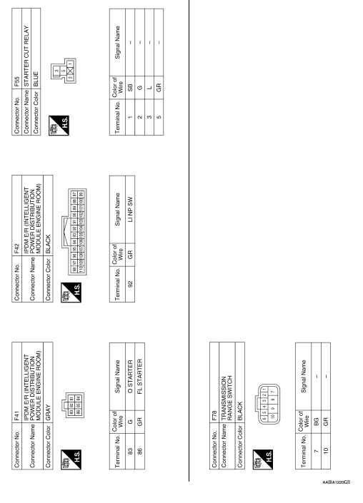
Wiring Diagram
 System
System Description
The starter motor plunger closes and provides a closed circuit between the
battery and the starter motor. The
starter motor is grounded to the cylinder block. With power and gro ...
 Basic inspection
DIAGNOSIS AND REPAIR WORKFLOW
Work Flow (With GR8-1200 NI)
STARTING SYSTEM DIAGNOSIS WITH GR8-1200 NI
To test the starting system, use the following special service tool:
GR8-1200 NI Mult ...
Other materials:
Special Cautions to Ensure the Safe Disposal of Sodium-filled Exhaust
Valves
Handling and disposal of sodium-filled exhaust valves requires special
care and consideration. Under conditions such as breakage with
subsequent contact with water, metal sodium which lines the inner
portion of exhaust valve will react violently, forming sodium hydroxide
and hydrogen which may r ...
Precaution
Precaution for Supplemental Restraint System (SRS) "AIR BAG" and "SEAT
BELT
PRE-TENSIONER"
The Supplemental Restraint System such as “AIR BAG” and “SEAT BELT PRE-TENSIONER”,
used along
with a front seat belt, helps to reduce the risk or severity of injury to the
...
Engine compartment check locations
QR25DE engine
Engine coolant reservoir
Engine oil filler cap
Brake fluid reservoir
Battery
Air cleaner
Fuse/Fusible link box
Radiator cap
Engine oil dipstick
Drive belt location
Windshield-washer fluid reservoir ...
