Nissan Rogue Service Manual: Wiring diagram
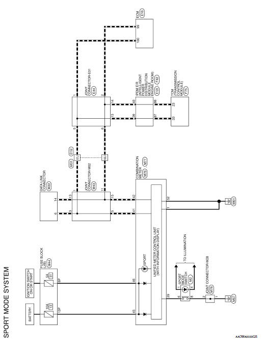
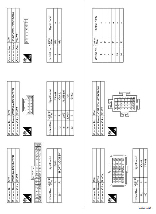
SPORT MODE SYSTEM
Wiring Diagram
 ECU diagnosis information
SPORT MODE
List of ECU Reference
...
 Basic inspection
DIAGNOSIS AND REPAIR WORK FLOW
Work Flow
DETAILED FLOW
1.OBTAIN INFORMATION ABOUT SYMPTOM
Interview the customer to obtain as much information as possible about the
conditions and environment un ...
Other materials:
Combination meter
Removal and Installation
REMOVAL
Disconnect the negative battery terminal. Refer to PG-77, "Removal
and Installation".
Remove the cluster lid A. Refer to IP-20, "Removal and
Installation".
Remove screws (A), from the combination meter (1).
...
Refrigerant pressure sensor
Component Function Check
1.CHECK REFRIGERANT PRESSURE SENSOR FUNCTION
Start engine and warm it up to normal operating temperature.
Turn A/C switch and blower fan switch ON.
Check the voltage between ECM harness connector terminals under
the following conditions.
...
CAN system (type 8)
MAIN LINE BETWEEN IPDM-E AND DLC CIRCUIT
Diagnosis Procedure
1.CHECK CONNECTOR
Turn the ignition switch OFF.
Disconnect the battery cable from the negative terminal.
Check the following terminals and connectors for damage, bend and
loose connection (connector side
an ...
