Nissan Rogue Service Manual: Wheel alignment
Inspection
DESCRIPTION
- Measure wheel alignment under unladen conditions.
NOTE: “Unladen conditions” means that fuel, engine coolant, and lubricants are full. Spare tire, jack, hand tools and mats are in designated positions.
PRELIMINARY CHECK
Check the following:
- Tires for improper air pressure and wear. Refer to WT-65, "Tire Air Pressure".
- Wheels for runout, deformation, cracks, or other damage. Refer to WT-56, "Inspection".
- Wheel bearings for axial end play. Refer to RAX-8, "Inspection" (FWD), RAX-18, "Inspection" (AWD).
- Shock absorbers for proper operation.
- Each suspension component for cracks, looseness, deformation, and other damages.
- Wheelarch height. Refer to RSU-24, "Wheelarch Height (Unladen*)".
GENERAL INFORMATION AND RECOMMENDATIONS
- A four-wheel thrust alignment should be performed.
- This type of alignment is recommended for any NISSAN/INFINITI vehicle.
- The four-wheel “thrust” process helps ensure that the vehicle is properly aligned and the steering wheel is centered.
- The alignment rack itself should be capable of accepting any NISSAN/INFINITI vehicle.
- The rack should be checked to ensure that it is level.
- Make sure the machine is properly calibrated.
- Your alignment equipment should be regularly calibrated in order to give correct information.
- Check with the manufacturer of your specific equipment for their recommended Service/Calibration Schedule.
ALIGNMENT PROCESS
IMPORTANT: Use only the alignment specifications listed in this Service Manual RSU-24, "Wheel Alignment (Unladen*1)".
- When displaying the alignment settings, many alignment machines use “indicators”: (Green/red, plus or minus, Go/No Go). Do not use these indicators.
- The alignment specifications programmed into your machine that operate these indicators may not be correct.
- This may result in an ERROR.
- Most camera-type alignment machines are equipped with both “Rolling Compensation” method and optional “Jacking Compensation” method to “compensate” the alignment targets or head units. “Rolling Compensation” is the preferred method.
- If using the “Rolling Compensation” method, after installing the alignment targets or head units, push or pull on the rear wheel to move the vehicle. Do not push or pull on the vehicle body.
- If using the “Jacking Compensation” method, after installing the alignment targets or head units, raise the vehicle and rotate the wheels 1/2 turn both ways.
NOTE: Do not use the “Rolling Compensation” method if you are using sensor-type alignment equipment.
- Follow all instructions for the alignment machine you're using for more information.
Adjustment
CAMBER
If camber is outside the standard value, adjust with adjusting bolt (1) in lower link (2).
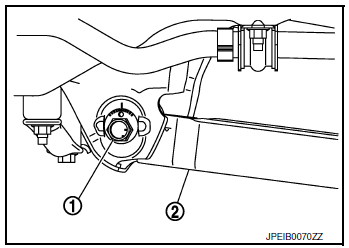
Camber: Refer to RSU-6, "Adjustment".
CAUTION: After adjusting camber, be sure to check toe-in.
TOE-IN
- If toe-in is not within the specification, adjust with adjusting bolt (1) in suspension arm (2).
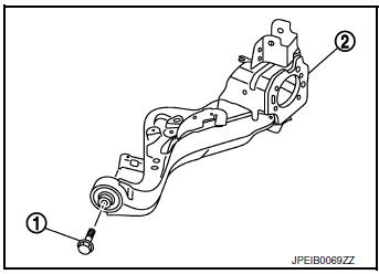
Toe-In: Refer to RSU-6, "Adjustment"
CAUTION:
- Be sure to adjust equally on RH and LH side with adjusting bolt.
- When tightening the nut firmly and checking the torque, use a wrench to prevent the turning of the bolt.
- If toe-in is not still within the specification, inspect and replace any damaged or worn suspension parts.
- - After toe-in adjustment, adjust neutral position of steering angle sensor. Refer to BRC-70, "Work Procedure".
 Rear suspension assembly
Inspection and Adjustment
COMPONENT PART
Check the conditions (looseness, backlash) of each component and component
conditions (wear, damage)
are normal.
SHOCK ABSORBER
Check the shock absorber ...

Other materials:
P0456 EVAP control system
DTC Description
DTC DETECTION LOGIC
This diagnosis detects leaks in the EVAP line between fuel tank and EVAP
canister purge volume control solenoid
valve, using the negative pressure caused by decrease of fuel temperature in the
fuel tank after turning
ignition switch OFF.
If ECM judges t ...
Roof rack
Exploded View
Roof rack rear bolt cover
Roof rack front bolt cover
Roof rack
Roof side molding
Back door hinge cover
Metal Clip
Pawl
Removal and Installation
REMOVAL
Release pawls and remove roof rack front and rear cover (1)
using suitable tool (A ...
Parking brake
WARNING
Be sure the parking brake is fully released
before driving. Failure to do so
can cause brake failure and lead to an
accident.
Do not release the parking brake from
outside the vehicle.
Do not use the shift lever in place of the
parking ...
