Nissan Rogue Service Manual: Washer level switch signal circuit
Description
Transmits the washer fluid level switch signal to the combination meter.
Diagnosis Procedure
Regarding Wiring Diagram information, refer to MWI-32, "Wiring Diagram".
1.CHECK WASHER FLUID LEVEL SWITCH SIGNAL CIRCUIT
- Turn ignition switch OFF.
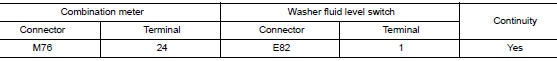
- Disconnect combination meter harness connector M76 and washer fluid level switch harness connector E82.
- Check continuity between combination meter harness connector M76 and washer fluid level switch harness connector E82.
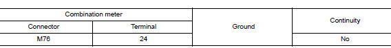
- Check continuity between combination meter harness connector and ground.
Is the inspection result normal? YES >> GO TO 2.
NO >> Repair or replace harness or connector.
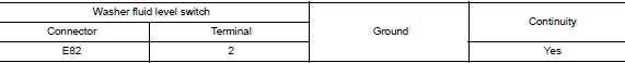
2.CHECK WASHER FLUID LEVEL SWITCH GROUND CIRCUIT
Check continuity between washer fluid level switch connector and ground.
Is the inspection result normal? YES >> Inspection End.
NO >> Repair or replace harness or connector.
Component Inspection
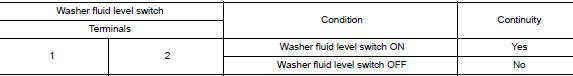
1.CHECK WASHER FLUID LEVEL SWITCH
- Turn ignition switch OFF.
- Disconnect washer fluid level switch connector.
- Check washer fluid level switch.
Is the inspection result normal?
YES >> Inspection End.
NO >> Replace washer fluid level switch. Refer to WW-58, "Removal and Installation".
 Steering switch
Description
When one of the steering switches is pushed, the resistance in the steering
switch changes the signal to
identify which button is controlling the information display.
Diagnosis Proced ...

Other materials:
Off-road recovery
If the right side or left side wheels unintentionally
leave the road surface, maintain control of the
vehicle by following the procedure below. Please
note that this procedure is only a general guide.
The vehicle must be driven as appropriate based
on the conditions of the vehicle, road and t ...
ECU diagnosis information
FRONT AIR CONTROL
Reference Value
TERMINAL LAYOUT
PHYSICAL VALUES
DTC Inspection Priority Chart
If some DTCs are displayed at the same time, perform inspections one by one
based on the following priority
chart.
Priority
Detected items (DTC)
1
...
Tow truck towing
CAUTION:
All applicable state or Provincial (in Canada) laws and local
laws regarding the towing operation
must be obeyed.
It is necessary to use proper towing equipment to avoid
possible damage to the vehicle during towing
operation. Towing is in accordance with Towing P ...
