Nissan Rogue Service Manual: Unit disassembly and assembly
STEERING GEAR AND LINKAGE
Exploded View
DISASSEMBLY AND ASSEMBLY
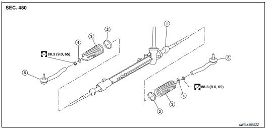
- Steering gear
- Inner boot clamp
- Boot
- Outer boot clamp
- Outer socket
Disassembly and Assembly
DISASSEMBLY
- Remove outer socket lock nut and remove outer socket.
- Remove inner and outer boot clamps and remove boot.
ASSEMBLY
- Apply recommended grease to inner socket.
- Install boot to steering gear.
- Install inner boot clamp (1) to boot and secure using Tool (A).
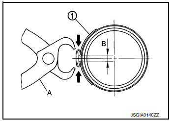
Tool number : (KV40107300) ( — )
CAUTION:
- Install inner boot clamp (1) securely to boot groove, and crimp it so as to have clearance (B) of 3 mm (0.12 in) or less as shown.
- Inspect boot clamps and replace as necessary.
- Install outer boot clamp to boot.
CAUTION: Inspect boot and replace as necessary.
- Install outer socket (3) and lock nut (2) to achieve length (A).
Check that inner socket (1) and outer socket (3) measure to standard length (B), then tighten lock nut (2) to the specified torque. Check length again after tightening lock nut (2).
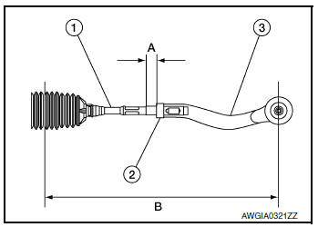
B : Refer to ST-19, "Steering Gear".
CAUTION:
- Adjust toe-in after this procedure. Length achieved after toe-in adjustment is not necessary the value above.
- When tightening lock nut, be sure to fix outer socket with a wrench or equivalent to prevent ball joint from getting contact with knuckle.
 Steering gear and linkage
Exploded View
REMOVAL AND INSTALLATION
Cotter pin
Steering gear
Heat shiel
Removal and Installation
REMOVAL
Set the front wheels and tires to the straight-ahea ...
 Service data and specifications (SDS)
Steering Wheel
Steering Angle
Steering Column
STEERING COLUMN LENGTH
STEERING COLUMN ROTATING TORQUE
TILT MECHANISM OPERATING RANGE
Steering Gear
STEERING OUTER SOCKET AND I ...
Other materials:
Main power window and door lock/unlock switch
Removal and Installation
REMOVAL
Remove the front door pull handle bracket (LH). Refer to INT-15,
"Removal and Installation".
Release pawls using a suitable tool (A) and remove main power
window and door lock/unlock switch finisher (1).
: Pawl
Disconnect t ...
Inspection and adjustment
ADDITIONAL SERVICE WHEN REMOVING BATTERY NEGATIVE TERMINAL
ADDITIONAL SERVICE WHEN REMOVING BATTERY NEGATIVE TERMINAL : Description
If any of the following work has been done Initial setting is necessary.
Power supply to the main power window and door lock/unlock switch
or power windo ...
Towing recommended by NISSAN
All-Wheel Drive (AWD) models
NISSAN recommends that towing dollies be
used when towing your vehicle or the vehicle be
placed on a flatbed truck as illustrated.
CAUTIONDO NOT tow AWD models with any of the
wheels on the ground as this may cause
serious and expensive damage to the ...
