Nissan Rogue Service Manual: Unit disassembly and assembly
REAR DRIVE SHAFT
Exploded View
DISASSEMBLY
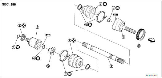
- Circular clip
- Dust shield
- Slide joint housing
- Snap ring
- Spider assembly
- Boot band
- Boot
- Shaft
- Circular clip
- Joint sub-assembly
- Sensor rotor
 : Wheel side
Disassembly and Assembly
DISASSEMBLY
Final Drive Side
- Place drive shaft in a vise.
CAUTION: When placing drive shaft in a vise, always use copper or aluminum plates between vise and shaft.
- Remove boot bands and slide boot back.
- Put matching marks on slide joint housing and shaft, and then pull out
slide joint housing from shaft.
CAUTION: Use paint or an equivalent for matching marks. Do not scratch the surface.
- Put matching marks (A) on the spider assembly and shaft.
CAUTION: Use paint or an equivalent for matching marks. Do not scratch the surface.
- Remove snap ring (1).
- Remove spider assembly from shaft.
- Remove boot from shaft.
- Remove circular clip from housing.
- Remove dust shield from housing.
- Remove old grease from housing using paper waste.
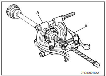
Wheel Side
- Remove sensor rotor using suitable tools (A) and (B).
- Place drive shaft in a vise.
CAUTION: When placing drive shaft in a vice, always use aluminum or copper plates between the vise and the drive shaft.
- Remove boot bands and slide boot back.
- Install suitable tool (A) 30 mm (1.18 in) or more into the thread of joint sub-assembly, and pull joint sub-assembly with suitable tool (B) from shaft.
CAUTION:
- Align sliding hammer and drive shaft and remove them by pulling forcibly.
- If joint sub-assembly cannot be removed after five or more unsuccessful attempts, replace shaft and joint sub assembly as a set.
- Remove circular clip from shaft.
CAUTION: Do not reuse circular clip.
- Remove boot from shaft.
- Clean old grease from joint sub-assembly while rotating ball cage.
INSPECTION AFTER DISASSEMBLY
Shaft
Check shaft for runout, cracks, or other damage. Replace components as necessary.
Joint Sub-Assembly (Wheel Side)
Check the following:
- Joint sub-assembly for rough rotation and excessive axial looseness.
- The inside of the joint sub-assembly for entry of foreign material.
- Joint sub-assembly for compression scars, cracks, and fractures inside of joint sub-assembly.
Replace joint sub-assembly if necessary.
Slide joint housing and spider assembly (Final Drive Side)
Replace slide joint housing and spider assembly if there is scratching or wear on the slide joint housing roller contact surface or spider roller contact surface.
NOTE: Slide joint housing and spider assembly are used in a set.
ASSEMBLY
Final Drive Side
- Install new boot and new small boot band to shaft.
CAUTION:
- Cover drive shaft serration with tape to prevent damage to boot during installation.
- Do not reuse boot or boot band.
- Remove the tape wrapped around the serration on shaft.
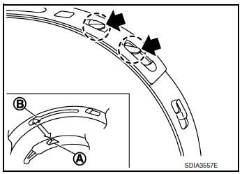
- Align the matching marks (A) on the spider assembly (1) with the matching mark on the shaft (2). Install the spider assembly to the shaft with the chamfer (B) facing the shaft.
- Install new snap ring (1) using suitable tool onto shaft.
CAUTION: Do not reuse snap ring.
- Apply the appropriate amount of grease (Genuine NISSAN
Grease or equivalent) onto the spider assembly and the sliding
surface of the slide joint housing.
NOTE: Always check with the Parts Department for the latest parts information.
- Install the slide joint housing onto the spider assembly and apply the balance of the specified amount of grease into the slide joint housing.
Grease amount : Refer to RAX-27, "Drive Shaft".
- Align the matching mark on the slide joint housing with the matching mark on the shaft.
- Install boot securely into grooves (indicated by “*” marks) as
shown.
CAUTION: If there is grease on boot mounting surfaces (indicated by “*” marks) on shaft or slide joint housing, the boot may come off. Clean all grease from the boot mounting surfaces.
- Make sure the boot installation length (L) is correct. Insert a suitable tool into large end of boot. Bleed air from boot to prevent boot deformation.
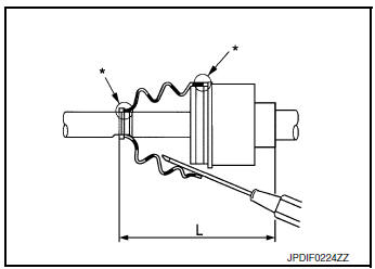
Boot installation length (L) : Refer to RAX-27, "Drive Shaft".
CAUTION:
- The boot may break if boot installation length is not correct.
- Be careful not to touch the inside of the boot with the tip of suitable tool.
- Install new boot bands securely.
CAUTION: Do not reuse boot band.
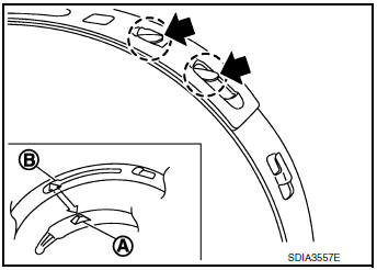
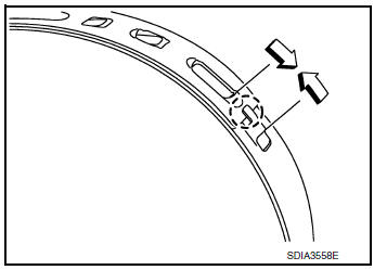
- Put boot band in the groove on drive shaft boot. Then fit pawls
(
 ) into holes for temporary
installation.
) into holes for temporary
installation.
NOTE: For the large diameter side, fit projection (A) and guide slit (B) at first.
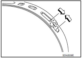
- Pinch projection on the band with suitable pliers to tighten band.
- Insert tip of band below end of pawl.
- Attempt to rotate boot to check whether or not the boot bands are securing the boot. If the boot is not secure, remove the boot bands, reposition the boot, and install new boot bands.
- Install dust shield to slide joint housing.
CAUTION: Do not reuse dust shield.
- Install circular clip to slide joint housing.
CAUTION: Do not reuse circular clip.
Wheel Side
- Install sensor rotor (1) using Tool (A), Tool (B) and a press.
Tool (A) number : KV38100500 ( - )
Tool (B) number : KV40101840 ( - )
- Fill the serration slot on the joint sub-assembly (1) with grease (Genuine NISSAN Grease or equivalent) until the serration slot and ball groove become full to the brim.
CAUTION: After applying the grease, use a paper shop cloth to wipe off the grease that has oozed out.
NOTE: Always check with the Parts Department for the latest parts information.
- Install new boot and new small boot band to shaft.
CAUTION:
- Cover drive shaft serration with tape to prevent damage to boot during installation.
- Do not reuse boot and boot band.
- Remove protective tape wrapped around the serration part on shaft.
- Install a new circular clip to shaft. Position the circular clip in the
shaft groove.
CAUTION: Do not reuse circular clip.
NOTE: A drive joint inserter is recommended when installing the circular clip.
- Align the center axle with the shaft edge and the joint
sub-assembly. Assemble the shaft with the joint-sub
assembly while holding the circular clip.
CAUTION: Confirm that joint sub-assembly is correctly engaged while rotating drive shaft.
- Install the joint sub-assembly to the shaft using a suitable tool.
CAUTION:
- Make sure the circular clip is properly positioned on the groove of the joint sub-assembly.
- Confirm that the joint sub-assembly is correctly engaged while rotating the drive shaft.
- Apply the balance of the specified amount of grease to the inside of the boot from the large diameter side of the boot.
Grease amount : Refer to RAX-27, "Drive Shaft".
- Install the boot securely into grooves (indicated by “*” marks) as
shown.
CAUTION: If there is grease on the boot mounting surfaces (indicated by “*” marks) on the shaft or joint sub-assembly, the boot may come off. Remove all grease from the boot mounting surfaces.
- Make sure boot installation length (L) is correct. Insert a suitable tool into the large end of the boot. Bleed air from boot to prevent boot deformation.
Boots installation length (L) : Refer to RAX-27, "Drive Shaft".
CAUTION: The boot may break if the boot installation length is not correct.
- Install new boot bands securely.
CAUTION: Do not reuse boot band.
- Put boot band in the groove on drive shaft boot. Then fit pawls
(
 ) into holes for temporary
installation.
) into holes for temporary
installation.
NOTE: For the large diameter side, fit projection (A) and guide slit (B) at first.
- Pinch projection on the band with suitable pliers to tighten band.
- Insert tip of band below end of pawl.
- Attempt to rotate boot to check whether or not the boot bands are securing the boot. If the boot is not secure, remove the boot bands, reposition the boot, and install new boot bands.
 Removal and installation
REAR WHEEL HUB AND HOUSING
Exploded View
Axle housing
Suspension arm
Back plate
Hub bolt
Wheel hub and bearing
Wheel hub lock nut
Cotter pin
Disc brake rotor
Plug
...
 Service data and specifications (SDS)
Wheel Bearing
Drive Shaft
...
Other materials:
On board diagnostic (OBD) system
Diagnosis Description
This system is an on board diagnostic system that records exhaust
emission-related diagnostic information
and detects a sensors/actuator-related malfunction. A malfunction is indicated
by the malfunction indicator
lamp (MIL) and stored in ECU memory as a DTC. The diagnos ...
Lumbar support switch
Exploded View
Seat cushion outer finisher
Lumbar support switch
Clip
Pawl
Removal and Installation
REMOVAL
Using a suitable tool release clips and remove seat cushion
outer finisher (1).
: Clip
Disconnect harness connector from lumbar support switch.
...
Component parts
Component Parts Location
Instrument lower panel LH
No.
Component
Function
1
Combination meter
The combination meter transmittes the following signal via CAN
communications
to the TCM.
SPORT mode switch signal
...
