Nissan Rogue Service Manual: Unit disassembly and assembly
TRANSFER COVER
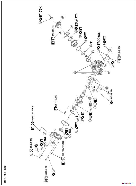
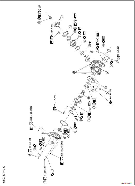
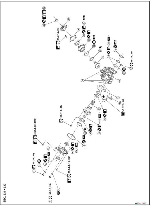
Exploded View
- Filler plug
- Gasket
- Drain plug
- Oil seal
- Transfer cover
- Oil seal
- O-ring
- Ring gear bearing adjusting shim (transfer cover side)
- Ring gear bearing (transfer cover side)
- Ring gear shaft oil seal
- Ring gear shaft
- Ring gear bearing (transfer case side)
- Ring gear bearing adjusting shim (transfer case side)
- Ring gear
- Baffle plate
- Transfer case
- Plug
- O-ring
- Oil seal
- Dowel pin
- Drive pinion
- Drive pinion adjusting shim
- O-ring
- Pinion bearing assembly
- Oil seal
- Dust cover
- Companion flange
- Pinion lock nut
- Oil seal lip
- Comply with the assembly procedure when tightening. Refer to DLN- 83, "Assembly".
 : N·m (kg-m, in-lb)
 : N·m (kg-m, ft-lb)
 : Always replace after every
disassembly.
: Always replace after every
disassembly.
 : Apply gear oil.
 *: Apply anti-corrosive oil.
 : Apply multi-purpose grease.
 : Select with proper thickness.
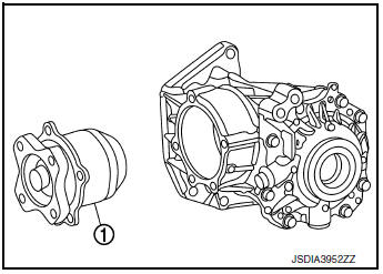
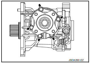
Disassembly
- Remove transfer cover mounting bolts (
 ).
).
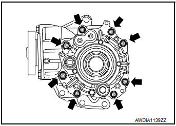
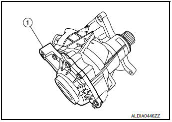
- Lightly tap transfer cover (1) with a plastic hammer to remove transfer cover.
- Remove O-ring from transfer cover.
CAUTION:
- Do not use a suitable tool.
- Do not damage transfer cover.
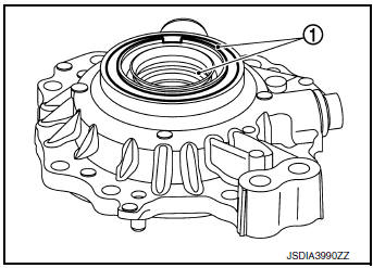
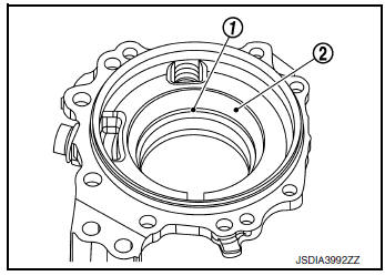
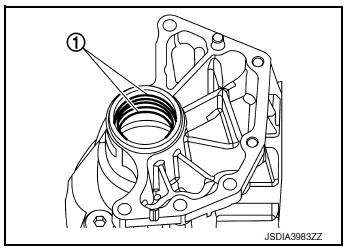
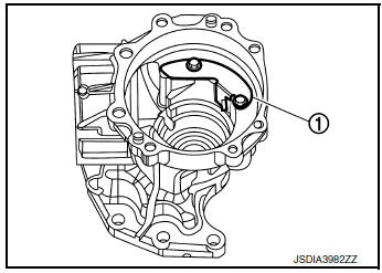
- Lightly tap the metal part of oil seals (1) with punch from back side of transfer cover to remove oil seals.
CAUTION: When removing, Do not damage the transfer cover by scooping it out with a suitable tool.
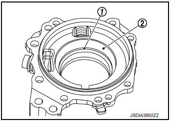
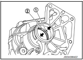
- Remove the ring gear bearing adjusting shim (transfer cover side) (1) and ring gear bearing outer race (transfer cover side) (2) using suitable tool.
- Remove drain plug and gasket.
- Remove filler plug and gasket.
- Perform inspection after disassembly. Refer to DLN-75, "Inspection".
Assembly
- Select the ring gear bearing adjusting shim (transfer cover side). Refer to DLN-84, "Adjustment".
- Install the selected ring gear bearing adjusting shim (transfer cover side) (1) and ring gear bearing outer race (transfer cover side) (2) using suitable tool.
CAUTION:
- Do not reuse ring gear bearing.
- Apply gear oil to the ring gear bearing.
- Install gasket onto drain plug and install them to transfer cover.
CAUTION: Do not reuse gasket.
- Install the transfer cover to the transfer case, and apply anti-corrosive oil onto thread and seats on the mounting bolts. Then tighten mounting bolts to the specified torque.
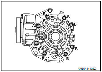
(A) : M10 bolt
(B) : M8 bolt
NOTE: At this timing, O-ring installing to transfer cover is not necessary.
Install O-ring after tooth contact is checked.
- Check backlash, tooth contact, total preload and companion
flange runout. Refer to DLN-84, "Adjustment".
CAUTION: Measure the total preload without oil seals of transfer cover and transfer case.
- Remove transfer cover to install O-ring.
- Apply multi-purpose grease lightly and evenly onto an O-ring, and install it to the transfer cover.
CAUTION:
- Do not reuse O-ring.
- When installing O-ring, do not use a suitable tool.
- Do not damage O-ring.
- Install the transfer cover to the transfer case, and apply anti-corrosive oil onto thread and seats on the mounting bolts. Then tighten mounting bolts to the specified torque.
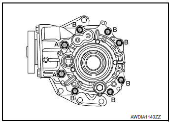
(A) : M10 bolt
(B) : M8 bolt
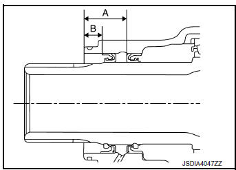
- Using suitable tool drive the transfer cover oil seals.
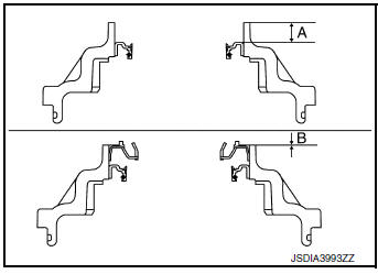
(A) : 10.3 +0.6/-0 mm (0.406 +0.024/-0 in)
(B) : 0 +0.6/-0 mm (0 +0.024/-0 in)
CAUTION:
- When checking the total preload torque, measure it without the oil seal, then install the oil seal.
- Do not reuse the oil seal.
- When installing, do not incline oil seal.
- Apply multi-purpose grease onto oil seal lips, and gear oil onto the circumference of the oil seal.
- Install gasket onto filler plug and install them to transfer cover.
CAUTION:
- Do not reuse gasket.
- Install filler plug after oil is filled.
Inspection
INSPECTION AFTER DISASSEMBLY
Check items below. If necessary, replace them with new ones.
Transfer cover
Check the bearing mounting surface for wear, cracks and damages.
RING GEAR SHAFT
Exploded View

- Filler plug
- Gasket
- Drain plug
- Oil seal
- Transfer cover
- Oil seal
- O-ring
- Ring gear bearing adjusting shim (transfer cover side)
- Ring gear bearing (transfer cover side)
- Ring gear shaft oil seal
- Ring gear shaft
- Ring gear bearing (transfer case side)
- Ring gear bearing adjusting shim (transfer case side)
- Ring gear
- Baffle plate
- Transfer case
- Plug
- O-ring
- Oil seal
- Dowel pin
- Drive pinion
- Drive pinion adjusting shim
- O-ring
- Pinion bearing assembly
- Oil seal
- Dust cover
- Companion flange
- Pinion lock nut
- Oil seal lip
- Comply with the assembly procedure when tightening. Refer to DLN- 83, "Assembly".
 : N·m (kg-m, in-lb)
 : N·m (kg-m, ft-lb)
 : Always replace after every
disassembly.
: Always replace after every
disassembly.
 : Apply gear oil.
 *: Apply anti-corrosive oil.
 : Apply multi-purpose grease.
 : Select with proper thickness.
Disassembly
- Remove transfer cover assembly. Refer to DLN-73, "Disassembly".
- Remove ring gear bearing outer race (transfer cover side) and ring gear bearing adjusting shim (transfer cover side) from the transfer cover. Refer to DLN-73, "Disassembly".
- Remove ring gear shaft assembly from the transfer case.
- Remove ring gear bearing outer race (transfer case side) and ring gear bearing adjusting shim (transfer case side) from the transfer case. Refer to DLN-90, "Disassembly".
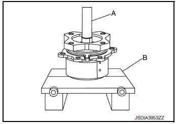
- Remove ring gear bearing inner race (transfer cover side) from ring gear shaft using suitable tool (A) and suitable tool.
- Remove ring gear bearing inner race (transfer case side) from ring gear shaft with suitable tool (A) and Tool.
Tool number : (KV381054S0) J-34286
- Remove the ring gear mounting bolts.
- Lightly tap ring gear with a plastic hammer to remove ring gear from the ring gear shaft.
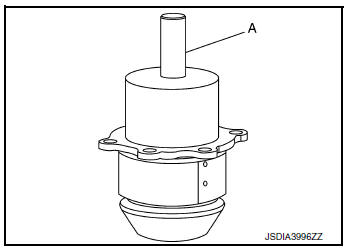
- Remove ring gear shaft oil seal from the ring gear shaft with the Tool (A).
Tool number : (KV381054S0) J-34286
- Perform inspection after disassembly. Refer to DLN-79, "Inspection".
Assembly
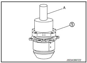
- Using suitable tool (A), install ring gear shaft oil seal (1) within the dimension (L) shown as follows.
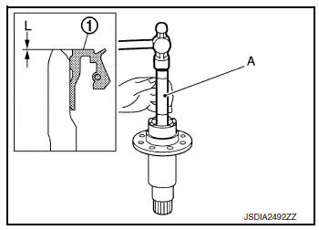
( L) : 2.0 +0.6/‚àí0 mm (0.079 +0.024/‚àí0 in)
CAUTION:
- Do not reuse the oil seal.
- When installing, do not incline oil seal.
- Apply multi-purpose grease onto oil seal lips, and gear oil onto the circumference of the oil seal.
- Select ring gear bearing adjusting shim (transfer case side) and ring gear bearing adjusting shim (transfer cover side). Refer to DLN-84, "Adjustment".
- Assemble the selected ring gear bearing adjusting shim (transfer case side) and ring gear bearing outer race (transfer case side) to transfer case. Refer to DLN-91, "Assembly".
CAUTION:
- Do not reuse ring gear bearing.
- Apply gear oil to the ring gear bearing.
- Assemble the selected ring gear bearing adjusting shim (transfer cover side) and ring gear bearing outer race (transfer cover side) to transfer cover. Refer to DLN-74, "Assembly".
CAUTION:
- Do not reuse ring gear bearing.
- Apply gear oil to the ring gear bearing.
- Install the ring gear to ring gear shaft, and tighten mounting bolts to the specified torque.
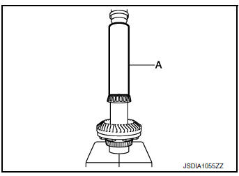
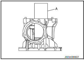
- Install ring gear bearing inner race (transfer cover side) with drift (A) (commercial service tool).
CAUTION:
- Do not reuse ring gear bearing.
- Apply gear oil to the ring gear bearing.
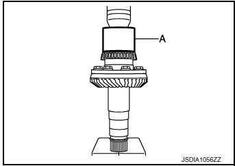
- Install the ring gear bearing inner race (transfer case side) to ring gear shaft with suitable tool (A).
CAUTION:
- Do not reuse ring gear bearing.
- Apply gear oil to the ring gear bearing.
- Install the ring gear shaft assembly to the transfer case.
CAUTION: Protect transfer case oil seals beforehand from being damaged by the spline of ring gear shaft below method following.
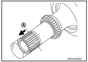
- Apply multi-purpose grease to spline part indicated in the figure.
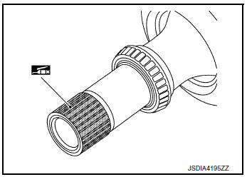
- Wrap piece of vinyl to spline part only indicated in the figure.
[(A): limit line]
CAUTION: Do not wrap sliding surfaces on oil seal.
- Install transfer cover to check and adjust each part. Refer to
DLN-74, "Assembly".
NOTE: At this timing, O-ring installing to transfer cover is not necessary.
Install O-ring after backlash and tooth contact are checked.
- Check backlash, tooth contact, total preload and companion
flange runout. Refer to DLN-84, "Adjustment".
CAUTION: Measure the total preload without oil seals of transfer cover and transfer case.
- Reinstall transfer cover for installing O-ring. Refer to DLN-74, "Assembly".
- After installing transfer case oil seals, remove wrapped vinyl from the spline of ring gear shaft.
Inspection
INSPECTION AFTER DISASSEMBLY
Check items below. If necessary, replace them with new ones.
Gear and Shaft
Check gear face and shaft for wear, cracks, damage, and seizure.
CAUTION: If malfunction is detected on the ring gear or drive pinion, replace the ring gear and drive pinion as a set.
Bearing
Check for seizure, peeling, wear, corrosion, sticking, unusual noise, roughness in hand turning, and other damage.
CAUTION: When replacing the bearing, always replace the inner race and outer race as a pair.
Shim
Check for seizure, damage, and unusual wear.
DRIVE PINION
Exploded View
- Filler plug
- Gasket
- Drain plug
- Oil seal
- Transfer cover
- Oil seal
- O-ring
- Ring gear bearing adjusting shim (transfer cover side)
- Ring gear bearing (transfer cover side)
- Ring gear shaft oil seal
- Ring gear shaft
- Ring gear bearing (transfer case side)
- Ring gear bearing adjusting shim (transfer case side)
- Ring gear
- Baffle plate
- Transfer case
- Plug
- O-ring
- Oil seal
- Dowel pin
- Drive pinion
- Drive pinion adjusting shim
- O-ring
- Pinion bearing assembly
- Oil seal
- Dust cover
- Companion flange
- Pinion lock nut
- Oil seal lip
- Comply with the assembly procedure when tightening. Refer to DLN- 83, "Assembly".
 : N·m (kg-m, in-lb)
 : N·m (kg-m, ft-lb)
 : Always replace after every
disassembly.
: Always replace after every
disassembly.
 : Apply gear oil.
 *: Apply anti-corrosive oil.
 : Apply multi-purpose grease.
 : Select with proper thickness.
Disassembly
- Remove pinion bearing assembly mounting bolts.
- Lightly tap companion flange with a plastic hammer to remove drive pinion assembly (1).
- Remove the O-ring from pinion bearing.
- Remove the pinion lock nut.
- Remove drive pinion from pinion bearing assembly using suitable tool (A) and suitable tool (B).
- Remove adjusting shim.
- Remove companion flange.
- Remove the dust cover.
- Remove the oil seal.
- Perform inspection after disassembly. Refer to DLN-88, "Inspection".
Assembly
- Select drive pinion adjusting shim. Refer to DLN-84, "Adjustment".
- Assemble the selected drive pinion adjusting shim to drive pinion.
- Install the drive pinion to pinion bearing assembly using suitable tool.
CAUTION:
- Do not reuse pinion bearing assembly.
- Apply gear oil to pinion bearing part.
- Install oil seal to pinion bearing assembly using suitable tool (A).
CAUTION:
- Do not reuse the oil seal.
- When installing, do not incline oil seal.
- Apply multi-purpose grease onto oil seal lips, and gear oil onto the circumference of the oil seal.
- Install dust cover.
NOTE: Tighten dust cover together with pinion bearing assembly.
- Install companion flange (1) to pinion bearing using suitable tool (A).
- Apply anti-corrosive oil to the thread and seat of the lock nut, and adjust the pinion lock nut tightening torque and pinion bearing preload torque, using a preload gauge.
- Install pinion lock nut, and then tighten to the specified torque.
Pinion lock nut tightening torque : 90±9 N·m (9.2±0.92kg-m, 66±7 ft-lb)
CAUTION:
- Do not reuse pinion lock nut.
- Check that pinion lock nut is seated on the companion flange.
- After tightening pinion lock nut to the specified torque, retighten the pinion lock nut by 25 degrees.
- Measure the pinion bearing preload.
Pinion bearing preload : Refer to DLN-93, "Preload Torque".
- Apply multi-purpose grease lightly and evenly onto an O-ring, and install it to the pinion bearing assembly.
CAUTION:
- Do not reuse O-ring.
- When installing O-ring, do not use a suitable tool.
- Do not damage O-ring.
- Install drive pinion assembly, and apply anti-corrosive oil onto
thread and seats on the mounting bolts. Tighten to the specified
torque.
NOTE: Tighten dust cover together with pinion bearing assembly.
- Check backlash, tooth contact, total preload and companion
flange runout. Refer to DLN-84, "Adjustment".
CAUTION: Measure the total preload without oil seals of transfer cover and transfer case.
Adjustment
ADJUSTING SHIM SELECTION
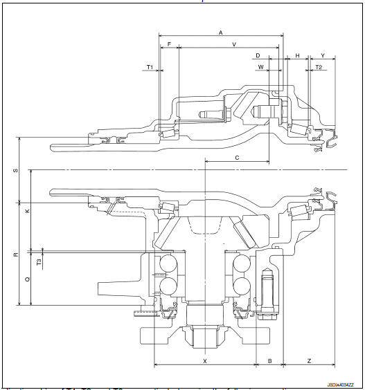
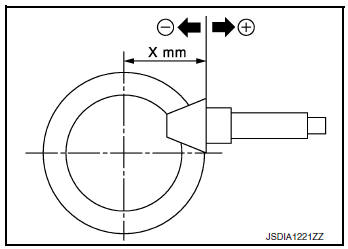
Measurement point
Select adjusting shim of T1, T2, and T3, respectively, by using the following equation.
T1 [Ring gear bearing adjusting shim (transfer case side)]
- T1 = A ‚àí(B +X/2) +C +W ‚àíV ‚àíF ‚àí(M/100) +0.071 mm (0.0028 in)
T2 [Ring gear bearing adjusting shim (transfer cover side)]
- T2 = ‚àíY +Z +(B +X/2) ‚àíC ‚àíD ‚àíH +(M/100) +0.071 mm (0.0028 in)
T3 (Drive pinion adjusting shim)
- T3 = ‚àíQ +(R +S/2) ‚àíK +(O/100)
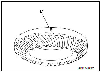
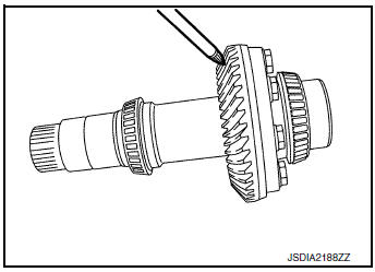
- Check dimension (M) on the ring gear side face.
NOTE: Dimension “M” indicates the difference between the optimum engagement and standard dimensions in increments of 0.01 mm (0.0004 in) written on the ring gear side face.
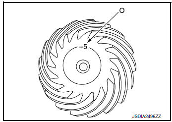
- Check dimension (O) on the gear end of drive pinion.
NOTE: Dimension “O” indicates the difference between the optimum engagement and the standard dimensions in increments of 0.01 mm (0.0004 in) written on the gear end of drive pinion.
PINION BEARING PRELOAD
CAUTION: When measuring preload, the rotating speed must be set to 30 rpm.
- Remove ring gear shaft assembly from the transfer case. Refer to DLN-77, "Disassembly".
- Rotate the companion flange back and forth from 2 to 3 times to check for unusual noise, binding, sticking, and so on.
- Rotate the companion flange at least 20 times to check for smooth operation of the bearing.
- Measure the pinion bearing preload using Tool A).
Pinion bearing preload : Refer to DLN-93, "Preload Torque".
Tool number : ST3127S000 (J-25765-A)
CAUTION: Each rotational part should rotate smoothly with the specified gear oil.
- If outside the standard, disassemble the drive pinion assembly to check and adjust each part.
TOTAL PRELOAD
CAUTION: When measuring preload, the rotating speed must be set to 30 rpm.
- Measure pinion bearing preload.
CAUTION: Check that the pinion bearing preload is within the standard.
- Assemble the ring gear shaft assembly to the transfer case. Refer to DLN-78, "Assembly"
- Install transfer cover to check and adjust each part. Refer to DLN-74, "Assembly".
- Rotate the companion flange at least 20 times to check for smooth operation of the bearing.
- Measure the total preload using Tool (A).
Total preload : Refer to DLN-93, "Preload Torque".
Tool number : ST3127S000 (J-25765-A)
CAUTION: Each rotational part should rotate smoothly with the specified gear oil.
- If outside the standard, disassemble the transfer assembly to check and adjust each part. Measure it with the transfer case oil seal and transfer cover oil seal removed when measuring total preload after disassembly. Then install transfer case oil seals and transfer cover oil seal.
BACKLASH
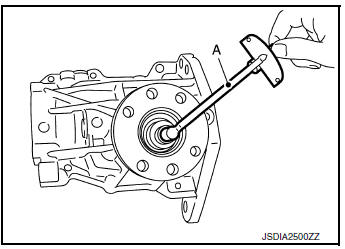
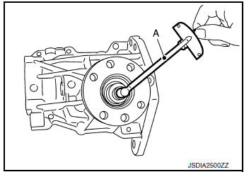
- Install the bolt to the companion flange.
- Fit a dial indicator onto the bolt (A).
- Measure the circumference backlash of the companion flange.
Backlash : Refer to DLN-93, "Backlash".
- If outside the standard, disassemble the transfer assembly to check and adjust each part.
TOOTH CONTACT
- Remove transfer cover. Refer to DLN-73, "Disassembly".
- Remove ring gear shaft assembly from transfer case. Refer to DLN-77, "Disassembly".
- Apply red lead onto the ring gear.
CAUTION: Apply red lead to both faces of 3 to 4 gears at 4 locations evenly spaced on the ring gear.
- Assemble the ring gear shaft assembly to the transfer case.
Refer to DLN-78, "Assembly".
- Install transfer cover to check and adjust each part. Refer to
DLN-74, "Assembly".
NOTE: At this timing, O-ring installing to transfer cover is not necessary.
Install O-ring after backlash and tooth contact are checked.
- Remove the plug from the transfer case.
- Rotate the companion flange back and forth several times, and check the drive pinion gear to ring gear tooth contact by viewing from the plug hole.
Tooth Contact Judgment Guide
- Follow the procedure below to adjust pinion height (dimension X) if tooth contact is improper. For selecting adjusting shim, refer to the latest parts information.
CAUTION: If no adjusting shim with the calculated value is available, select the thicker and closest one.
- Thicken the drive pinion adjusting shim to move the drive pinion closer to the ring gear in case of face contact or heel contact.
CAUTION: Only one adjusting shim can be selected.
- Thin the drive pinion adjusting shim to move the drive pinion farther from the ring gear in case of flank contact or toe contact.
CAUTION: Only one adjusting shim can be selected.
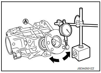
COMPANION FLANGE RUNOUT
- Fit a dial indicator onto the companion flange face (inner side of the propeller shaft mounting bolt holes).
- Rotate the companion flange to check for runout.
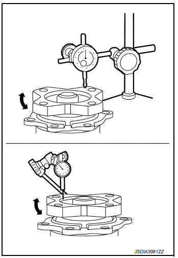
Companion flange runout : Refer to DLN-93, "Companion Flange Runout".
- Fit suitable tool to the inner side of the companion flange (socket diameter).
- Rotate the companion flange to check for runout.
Companion flange runout : Refer to DLN-93, "Companion Flange Runout".
- Follow the procedure below to adjust if runout value is outside the repair limit.
- Check for runout while changing the phase between companion flange and drive pinion in 90° steps. Then search for the minimum point.
- Replace companion flange if runout value is still outside the limit after the phase has been changed.
- Adjust assembly status of the pinion bearing and drive pinion, or replace pinion bearing assembly if runout is outside the standard after the companion flange is replaced.
Inspection
INSPECTION AFTER DISASSEMBLY
Check items below. If necessary, replace them with new ones.
Gear and Shaft Check gear face and shaft for wear, cracks, damage, and seizure.
CAUTION: Replace ring gear and drive pinion as a set (hypoid gear set) if any malfunction is detected on the ring gear or drive pinion.
Bearing
Check for seizure, peeling, wear, corrosion, sticking, unusual noise, roughness in hand turning, and other damage.
Shim
Check for seizure, damage, and unusual wear.
TRANSFER CASE
Exploded View
- Filler plug
- Gasket
- Drain plug
- Oil seal
- Transfer cover
- Oil seal
- O-ring
- Ring gear bearing adjusting shim (transfer cover side)
- Ring gear bearing (transfer cover side)
- Ring gear shaft oil seal
- Ring gear shaft
- Ring gear bearing (transfer case side)
- Ring gear bearing adjusting shim (transfer case side)
- Ring gear
- Baffle plate
- Transfer case
- Plug
- O-ring
- Oil seal
- Dowel pin
- Drive pinion
- Drive pinion adjusting shim
- O-ring
- Pinion bearing assembly
- Oil seal
- Dust cover
- Companion flange
- . Pinion lock nut
- Oil seal lip
- Comply with the assembly procedure when tightening. Refer to DLN- 83, "Assembly".
 : N·m (kg-m, in-lb)
 : N·m (kg-m, ft-lb)
 : Always replace after every
disassembly.
: Always replace after every
disassembly.
 : Apply gear oil.
 *: Apply anti-corrosive oil.
 : Apply multi-purpose grease.
 : Select with proper thickness.
Disassembly
- Remove transfer cover. Refer to DLN-73, "Disassembly".
- Remove ring gear shaft assembly. Refer to DLN-77, "Disassembly".
- Remove drive pinion assembly. Refer to DLN-82, "Disassembly".
- Remove O-ring from transfer case.
CAUTION:
- Do not use a suitable tool.
- Do not damage transfer case.
- 5. Remove oil seals (1).
CAUTION: Do not damage transfer case.
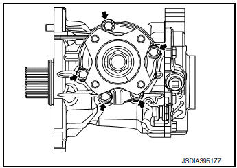
- Remove baffle plate (1).
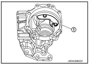
- Remove the ring gear bearing adjusting shim (transfer case
side) (1) and ring gear bearing outer race (transfer case side) (2)
by tapping from the 2 cutouts (
 ) on the transfer case.
CAUTION: Do not damage transfer case.
- Remove plug and gasket.
- Perform inspection after disassembly. Refer to DLN-92, "Inspection".
Assembly
- Select the ring gear bearing adjusting shim (transfer case side). Refer to DLN-84, "Adjustment".
- Install the selected ring gear bearing adjusting shim (transfer case side) and ring gear bearing outer race (transfer case side) using suitable tool (A).
CAUTION:
- Do not reuse ring gear bearing.
- Apply gear oil to the ring gear bearing.
- Install baffle plate (1).
- Install ring gear shaft assembly. Refer to DLN-78, "Assembly".
CAUTION: Protect transfer case oil seals beforehand from being damaged by the spline of ring gear shaft.
- Install drive pinion assembly. Refer to DLN-83, "Assembly".
- Install transfer cover to check and adjust each part. Refer to
DLN-74, "Assembly".
NOTE: At this timing, O-ring installing to transfer cover is not necessary.
Install O-ring after backlash and tooth contact are checked.
- Check backlash, tooth contact, total preload and companion flange
runout. Refer to DLN-84, "Adjustment".
CAUTION: Measure the total preload without oil seals of transfer cover and transfer case.
- Reinstall transfer cover for installing O-ring. Refer to DLN-74, "Assembly".
- Install oil seals using suitable tool.
(A) : 24.8 mm (0.976 in)
(B) : 10.3 mm (0.406 in)
CAUTION:
- When checking the total preload torque, measure it without the oil seal, then install the oil seal.
- Do not reuse the oil seal.
- When installing, do not incline oil seal.
- Apply multi-purpose grease onto oil seal lips, and gear oil onto the circumference of the oil seal.
- Do not damage oil seals by spline of ring gear shaft.
- After installing oil seals to transfer case, remove wrapped vinyl from the spline of ring gear shaft.
- Apply multi-purpose grease lightly and evenly onto an O-ring, and install it to the transfer case.
CAUTION:
- Do not reuse O-ring.
- When installing O-ring, do not use a suitable tool.
- Do not damage O-ring.
Inspection
INSPECTION AFTER DISASSEMBLY
Check items below. If necessary, replace them with new ones.
Case
Check the bearing mounting surface for wear, cracks and damages.
 Unit removal and installation
TRANSFER ASSEMBLY
Exploded View
1 Transfer assembly
: N·m (kg-m, ft-lb)
*: Apply anti-corrosion oil.
Removal and Installation
NOTE:
When removing components such as hoses, tubes/lines, etc ...
 Service data and specifications (SDS)
General Specifications
Preload Torque
Backlash
Companion Flange Runout
...
Other materials:
Precaution
Precaution for Supplemental Restraint System (SRS) "AIR BAG" and "SEAT
BELT
PRE-TENSIONER"
The Supplemental Restraint System such as “AIR BAG” and “SEAT BELT PRE-TENSIONER”,
used along
with a front seat belt, helps to reduce the risk or severity of injury to the
...
Headlight control switch
Type A (if so equipped)
When turning the switch to the
position,
the front parking, tail, license plate and
instrument panel lights come on.
When turning the switch to the
position,
the headlights come on and all the other
lights remain on.
Type B (if so equipped)
...
Precaution
Precaution for Supplemental Restraint System (SRS) "AIR BAG" and "SEAT
BELT
PRE-TENSIONER"
The Supplemental Restraint System such as “AIR BAG” and “SEAT BELT PRE-TENSIONER”,
used along
with a front seat belt, helps to reduce the risk or severity of injury to the
...
