Nissan Rogue Service Manual: Unit disassembly and assembly
FRONT COMBINATION LAMP
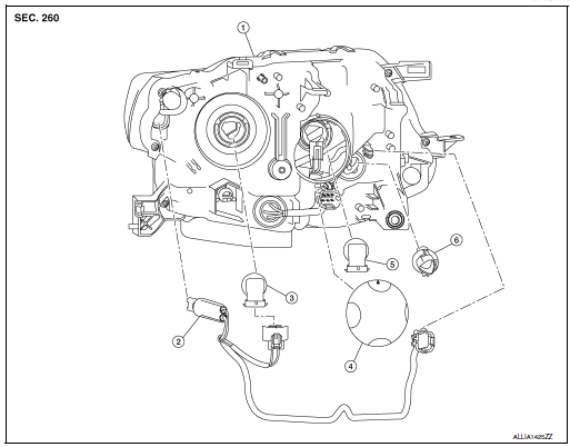
Exploded View

- Front combination lamp
- Parking (side marker) lamp bulb socket
- Headlamp (low beam) bulb
- Plastic cover
- Headlamp (high beam) bulb
- Turn signal lamp bulb socket
Disassembly and Assembly
DISASSEMBLY
- Remove front combination lamp. Refer to EXL-119, "Removal and Installation".
- Rotate the headlamp (low beam) bulb counterclockwise and remove.
- Disconnect the harness connector from headlamp (low beam) bulb.
- Remove plastic cover.
- Rotate the headlamp (high beam) bulb counterclockwise and remove.
- Disconnect the harness connector from headlamp (high beam) bulb.
- Rotate the parking (side marker) lamp bulb socket counterclockwise and remove.
- Remove the parking (side marker) lamp bulb from the bulb socket.
- Rotate the turn signal lamp bulb socket counterclockwise and remove.
- Remove the turn signal lamp bulb from the bulb socket.
ASSEMBLY
Assembly is in the reverse order of disassembly.
REAR COMBINATION LAMP
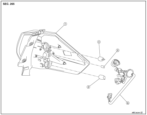
Exploded View

- Rear combination lamp
- Turn signal lamp bulb
- Tail lamp bulb
- Stop lamp bulb
- Rear combination lamp harness
Disassembly and Assembly
DISASSEMBLY
- Remove rear combination lamp. Refer to EXL-127, "Removal and Installation".
- Rotate the stop lamp bulb socket counterclockwise and remove.
- Remove the stop lamp bulb from the bulb socket.
- Rotate the tail lamp bulb socket counterclockwise and remove.
- Remove the tail lamp bulb from the bulb socket.
- Rotate the turn signal lamp bulb socket counterclockwise and remove.
- Remove the turn signal lamp bulb from bulb socket.
ASSEMBLY
Assembly is in the reverse order of disassembly.
CAUTION: After installing, be sure to install the bulb sockets securely to ensure watertightness.
 Removal and installation
FRONT COMBINATION LAMP
Exploded View
Front fender
Front combination lamp
Clip
Removal and Installation
REMOVAL
Remove front bumper fascia. Refer to EXT-17, "Removal an ...
 Service data and specifications (SDS)
Bulb Specifications
*: Always check with the Parts Department for the latest parts info. ...
Other materials:
Tire pressure
Tire Pressure Monitoring System
(TPMS)
WARNINGRadio waves could adversely affect electric
medical equipment. Those who use a
pacemaker should contact the electric
medical equipment manufacturer for the
possible influences before use
This vehicle is equipped with TPMS. It m ...
Speedometer and odometer
Speedometer
The speedometer indicates vehicle speed.
Odometer/Twin trip odometer
The odometer 1 and the twin trip odometer 2
are displayed below the Vehicle Information Display
when the ignition switch is placed in the ON
position.
The odometer records the total distance the vehicle
has ...
Brake booster
Exploded View
Spacer
Gasket
Brake booster
Check valve
Reservoir tank
Brake fluid level sensor
Brake booster pressure sensor
Removal and installation
REMOVAL
Remove the cowl top. Refer to EXT-25, "Removal and Installation".
Remove th ...
