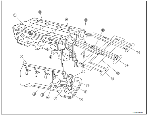
Nissan Rogue Service Manual: System description
DESCRIPTION
Engine Lubrication System

- Camshaft (INT)
- Chain tensioner
- Main gallery
- Oil pan
- Oil cooler
- Balancer unit
- Oil pan oil gallery
- Oil filter (with relief valve)
- Oil Strainer
- Oil pump
- Timing chain and balancer unit timing chain oil jet
- Intake valve timing intermediate lockcontrol solenoid valve
- Intake valve timing control cover
- Intake valve timing control solenoid valve
- Exhaust valve timing control solenoid valve
- Front cover
- Exhaust valve timing controller
- Intake valve timing controller
- Camshaft (EXH)
Engine Lubrication System Schematic

- Oil pan
- Oil strainer
- Oil pump
- Regulator valve
- Oil filter
- Relief valve (Built in oil filter)
- Oil cooler
- Relief valve
- Chain oil jet
- Main gallery
- Piston oil jet
- Cylinder head
- C-VTC oil filter
- C-VTC EXH solenoid valve
- C-VTC intermediate solenoid valve
- C-VTC INT solenoid valve
- C-VTC exhaust
- C-VTC intermediate
- C-VTC intake
- Camshaft journal
- Camshaft
- Chain tensioner
- Balancer housing
- Balancershaft journal
- Main bearing
- Crankshaft
- Connectiong rod bearing
- Connectiong rod
- Piston
 Preparation
Special Service Tools
The actual shape of the tools may differ from those illustrated here.
Tool number
(TechMate No.)
Tool name
Description
KV10111100
(J-37228)
...
Other materials:
B0094 crash zone sensor
DTC Logic
DTC DETECTION LOGIC
CONSULT name
DTC
DTC detecting condition
Repair order
CRASH ZONE SENSOR
[SENSOR FAIL]
B0094
Crash zone sensor has malfunctioned.
Refer to SRC-68, "Diagnosis Procedure".
CRASH ZONE SENSOR
[COMM ...
System
CHARGING SYSTEM
CHARGING SYSTEM : System Description
The generator provides DC voltage to operate the vehicle's electrical system
and to keep the battery charged.
The voltage output is controlled by the IC regulator.
SYSTEM DIAGRAM
POWER GENERATION VOLTAGE VARIABLE CONTROL SYSTEM
P ...
Fuel pump
Description
Sensor
Input signal to ECM
ECM Function
Actuator
Crankshaft position sensor (POS)
Camshaft position sensor (PHASE)
Engine speed*
Fuel pump control
Fuel pump relay↓
Fuel pump
Battery
Battery voltage*
*: ECM determines the st ...

