Nissan Rogue Service Manual: System description
COMPONENT PARTS
Component Parts Location
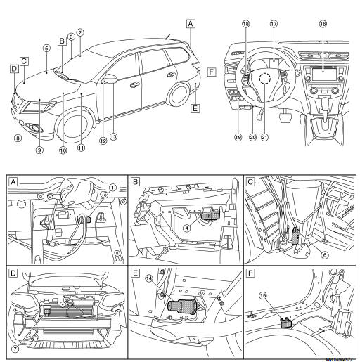
- View with back door finisher removed
- View with glove box assembly removed
- View with front bumper removed
- View with front bumper removed
- Rear under body LH
- View with luggage rear plate removed
|
No. |
Component |
Function |
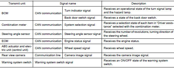
| 1 | Rear view camera | Refer to DAS-13, "Rear View Camera". |
| 2 | Side camera RH | Refer to DAS-14, "Side Cameras". |
| 3 | Blind spot warning indicator RH | Refer to DAS-14, "Blind Spot Warning Indicator LH/RH". |
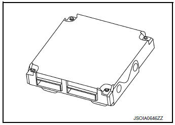
| 4 | Around View® Monitor control unit | Refer to DAS-13, "Around View Monitor Control Unit". |
| 5 | ABS actuator and electric unit (control unit) | Transmits the vehicle speed signal (wheel speed) to around view monitor via CAN communication Refer to BRC-8, "Component Parts Location" for detailed installation location. |
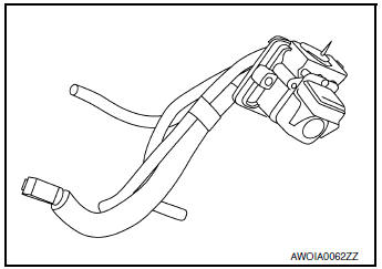
| 6 | Rear washer motor | Pumps washer fluid to the rear view camera |
| 7 | Distance sensor | Refer to DAS-12, "Distance Sensor". |
| 8 | Front camera | Refer to DAS-14, "Front Camera". |
| 9 | ECM |
|
| 10 | TCM | Refer to TM-12, "CVT CONTROL SYSTEM : Component Parts Location" for detailed installation location. |
| 11 | BCM | Transmits the turn indicator signal, dimmer signal, and back door
switch signal to around
view monitor via CAN communication. Refer to the following for detailed installation location:
|
| 12 | Blind spot warning indicator LH | Refer to DAS-14, "Blind Spot Warning Indicator LH/RH". |
| 13 | Side camera LH | Refer to DAS-14, "Side Cameras". |
| 14 | Rear view camera air pump motor | Refer to DAS-13, "Rear View Camera Air Pump Motor". |
| 15 | Rear view camera washer control unit | Refer to DAS-14, "Rear View Camera Washer Control Unit". |
| 16 | AV control unit | Receives the various systems and camera signals via CAN
communication and routes
them to the AV control unit display. Refer to AV-77, "Component Parts Location" for detailed installation location. |
| 17 | Combination meter |
|
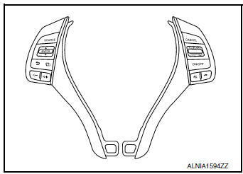
| 18 | Steering switch | Refer to DAS-13, "Steering Switch". |
| 19 | Warning system switch | Refer to DAS-15, "Warning System Switch". |
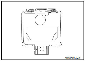
| 20 | Warning system buzzer | Refer to DAS-14, "Warning System Buzzer". |
| 21 | Steering angle sensor | Transmits the steering angle sensor signal to around view monitor
via CAN communication. Refer to BRC-8, "Component Parts Location" for detailed installation location. |
Distance Sensor
- Distance sensor is installed to the back of the front bumper and detects a vehicle ahead by using millimeter waves.
- Distance sensor detects radar reflected from a vehicle ahead by irradiating radar forward and calculates a distance from the vehicle ahead and relative speed, based on the detected signal.
- Distance sensor transmits the presence/absence of vehicle ahead and the distance from the vehicle to around view monitor control unit via CAN communication.
Steering Switch
- Steering switches are installed in the steering wheel.
- Settings for driver assistance systems are possible.
- Switch is connected to the combination meter and signals are transmitted to the around view monitor via CAN communication.
Around View Monitor Control Unit
- The around view monitor control unit is installed behind the glove box.
- Vehicle width guide lines, predicted course line, vehicle front guiding line and vehicle side line, and vehicle icon are displayed and combined with camera images.
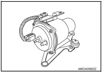
Rear View Camera Air Pump Motor
- Rear view camera air pump motor is installed to the rear left underbody.
- Air pump is activated and generates compressed air when power is supplied from the rear view camera washer control unit.
- Compressed air jets out from the air nozzle of rear view camera via air tube.
Combination Meter
- Displays the system status according to a signal received.
- Operates the buzzer according to the signal from the distance sensor.
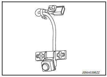
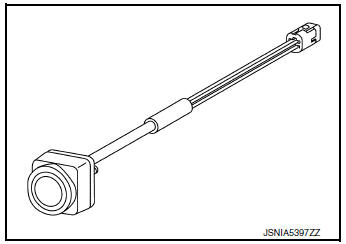
Rear View Camera
- The rear view camera is installed in the back door finisher.
- With the mirror processing function, a mirror image is sent as if it is viewed by a rear view mirror.
- Power for the camera is supplied from the around view monitor control unit, and the image at the rear of the vehicle is sent to the around view monitor control unit.
- The rear view camera is equipped with a washer nozzle and air nozzle for cleaning camera. A check valve is installed to the tube connected to the washer nozzle.
Front Camera
- The front camera is installed in the front grille.
- Power is supplied from the around view monitor control unit.
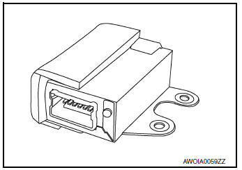
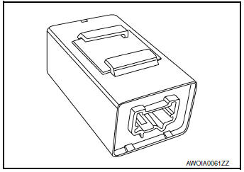
Rear View Camera Washer Control Unit
- Rear view camera washer control unit is installed under the luggage rear plate.
- Communicates with around view monitor control unit via serial communication line.
- Activates air pump an washer pump according to the signal from around view monitor control unit.
Warning System Buzzer
- Warning system buzzer is installed to the back of the instrument lower panel LH.
- When a warning buzzer signal is received from the around view monitor, the buzzer sounds.
Side Cameras
- The side cameras are installed in the door mirrors.
- Power is supplied from the around view monitor control unit.
Blind Spot Warning Indicator LH/RH
- Installed on the front door corner finisher, the blind spot warning indicator warns the driver by lighting/blinking.
- Receives a blind spot warning indicator operation signal from the around view monitor control unit.
Warning System Switch
- Installed to the back of the instrument lower panel LH, the warning system switch is used to activate/deactivate the driver assistance system.
- Transmits a warning system switch signal to the around view monitor control unit.
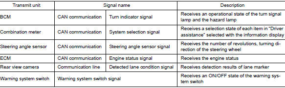
SYSTEM
LDW
LDW : System Description
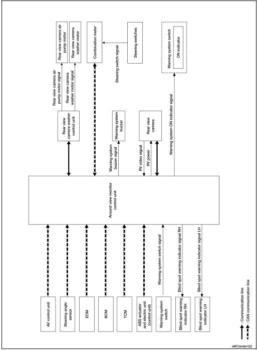
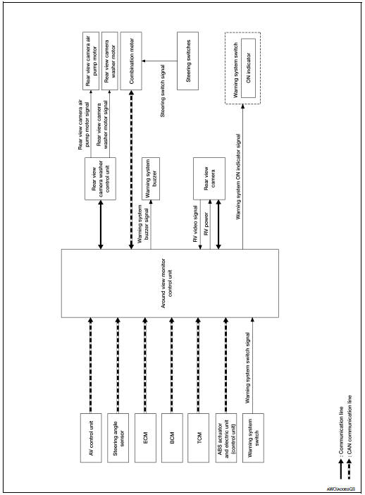
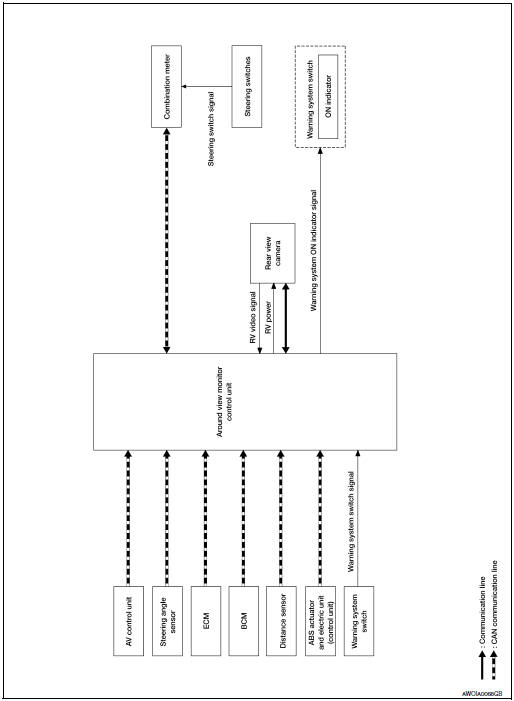
SYSTEM DIAGRAM
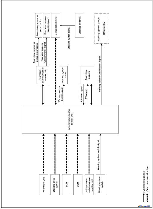
AROUND VIEW MONITOR CONTROL UNIT INPUT/OUTPUT SIGNAL ITEM
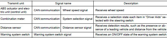
Input Signal Item
Output Signal Item
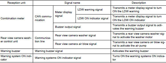
FUNCTION DESCRIPTION
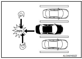
- Lane Departure Warning (LDW) system provides a lane departure warning function when the vehicle is driven at speeds of approximately 45 MPH (70 km/h) or more.
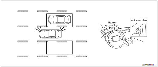
- When the vehicle approaches either the left or the right side of the traveling lane, a warning will sound and the lane departure warning lamp (orange) on the combination meter will blink to alert the driver.
- The warning does not occur during turn signal operation (Lane change side).
- The warning function will stop when the vehicle returns inside of the lane markers.
EXAMPLE
When the vehicle approaches the right lane marker, the driver is alerted by the buzzer and the blinking of lane departure warning lamp (orange).
OPERATION DESCRIPTION
- When the system is turned ON by operating the warning systems switch, around view monitor control unit turns ON the LDW ON indicator and the warning systems ON indicator.
- Rear view camera monitors the traveling lane. It transmits the camera image signal to around view monitor control unit.
- When judging from a camera image signal that the vehicle is approaching the lane marker, the around view monitor control unit controls the following item to alert the driver.
- Activates warning buzzer in the combination meter.
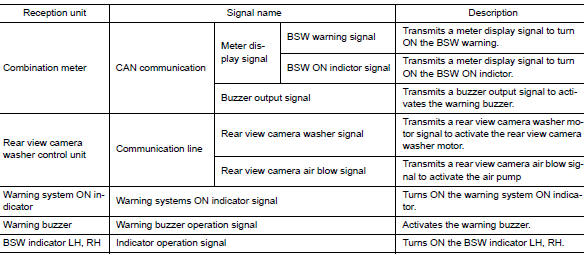
- Around view monitor control unit transmits a meter display signal to combination meter via CAN communication and turns ON/OFF the LDW warning.
Operating Condition
- LDW ON indicator: ON
- Warning systems ON indicator: ON
- Vehicle speed: approximately 45 MPH (70 km/h) or more
- Turn indicator signal: After 2 seconds or more from turned OFF
- Back door: Close
- Low washer fluid warning: OFF
NOTE:
- When the LDW system setting on the combination meter is ON.
- After the operating conditions of warning are satisfied, the warning continues until the vehicle speed reaches approximately 40 MPH (60 km/h)
- The LDW system may not function properly, depending on the situation. Refer to DAS-36, "Precautions for Lane Departure Warning".
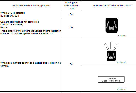
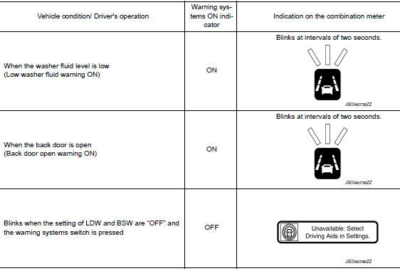
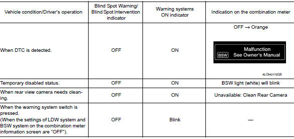
Fail-safe Indication
REAR VIEW CAMERA WASHER OPERATION
- When judging that the rear view camera has water droplets, the around view monitor control unit transmits a rear view camera washer activation signal or rear view camera air blow signal to the rear view camera washer control unit via serial communication.
- When receiving a rear view camera washer signal, the rear view camera washer control unit simultaneously activates the rear view camera washer motor to clean the rear view camera by spraying washer fluid from the nozzle installed to the rear view camera bracket.
- When receiving a rear view camera air blow signal, the rear view camera washer control unit activates the air pump to clean the rear view camera by blowing air from the nozzle installed to the rear view camera bracket.
OPERATION CONDITION
- Approximately 20 MPH (30 km/h) or more
- When the around view monitor control unit judges that the rear view camera has water droplets.
- When the low washer fluid warning is OFF.
NOTE: The camera is cleaned intermittently by spraying washer fluid and blowing air. When the around view monitor control unit judges that dirt on the camera cannot be removed even after approximately 5 minutes from the first detection of dirt, the activation of LDW is canceled.
BSW
BSW : System Description
SYSTEM DIAGRAM
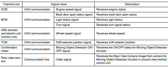
CONTROL UNIT INPUT/OUTPUT SIGNAL ITEM
Control unit receives signals via CAN communication. It also detects vehicle conditions that are necessary for BSW control.
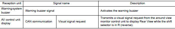
Input Signal Item
Output Signal Item
FUNCTION DESCRIPTION
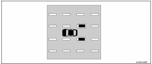
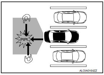
- The BSW system can help alert the driver of other vehicles in adjacent lanes when changing lanes.
- The BSW system uses rear view camera near the rear bumper to detect vehicles in an adjacent lane.
- The rear view camera can detect vehicles on either side of vehicle within the detection zone shown as illustrated.
- This detection zone starts from the back of the vehicle and extends approximately 10 ft. (3.0 m) behind the rear bumper, and approximately 10 ft. (13.0 m) sideways.
- The BSW system operates above approximately 20 MPH (32 km/h).
- If the rear view camera detects vehicles in the detection zone, the blind spot warning indicator illuminates.
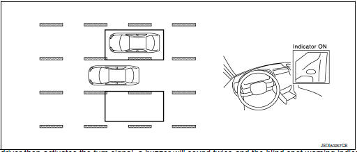
- If the driver then activates the turn signal, a buzzer will sound twice
and the blind spot warning indicator will
blink.
NOTE: A buzzer sounds if the rear view camera has already detected vehicles when the driver activates the turn signal. If a vehicle comes into the detection zone after the driver activates the turn signal, then only the blind spot warning indicator blinks and no buzzer sounds.
BSW SYSTEM OPERATION DESCRIPTION
- Control unit enables BSW system.
- The control unit turns on the BSW system when the warning systems switch is turned ON.
- Rear view camera detects a vehicle in the adjacent lane, and transmits the vehicle detection signal to control unit.
- Control unit starts the control as follows, based on a vehicle detection signal and turn signal transmitted from BCM via CAN communication:
- Buzzer signal transmission to warning buzzer.
- Around view monitor transmits a blind spot warning indicator signal LH or RH to the blind spot warning indicator LH or RH.
Operation Condition of BSW System
control unit performs the control when the following conditions are satisfied:
- When the warning system switch is turned ON*.
- When the vehicle drives at 20 MPH (32 km/h) or more in the forward direction.
NOTE: *: When the BSW system setting on the vehicle information display screen is ON.
- After the operating conditions of warning are satisfied, the warning continues until the vehicle speed is reduced below approximately 18 MPH (29 km/h)
- The BSW system may not function properly, depending on the situation.
BULB CHECK ACTION AND FAIL-SAFE INDICATION
*: Blinking cycle when there is a rear view camera blockage condition or lane camera unit high temperature condition
NOTE: Time shown in the figure is approximate.
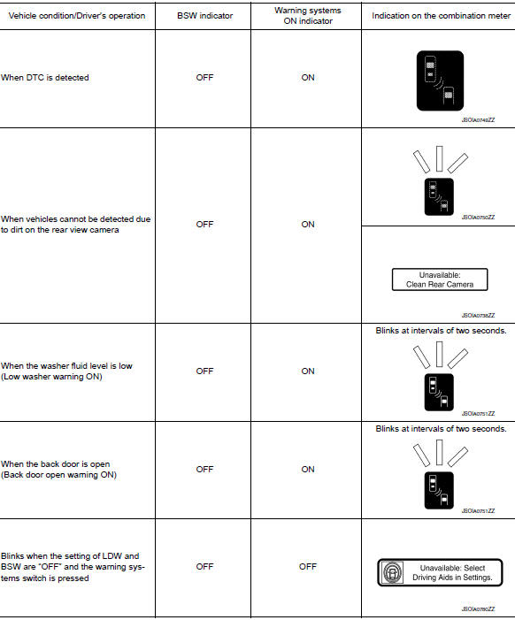
FAIL-SAFE INDICATION
REAR VIEW CAMERA WASHER OPERATION
- When judging that the rear view camera has water droplets, the around view monitor control unit transmits a rear view camera washer activation signal or rear view camera air blow signal to the pump control unit via serial communication.
- When receiving a rear view camera washer activation signal, the pump control unit simultaneously activates the washer pump to clean the rear view camera by spraying washer fluid from the nozzle installed to the rear view camera bracket.
- When receiving a rear view camera air blow signal, the pump control unit activates the air pump to clean the rear view camera by blowing air from the nozzle installed to the rear view camera bracket.
OPERATION CONDITION
- Approximately 20 MPH (30 km/h) or more
- When the around view monitor control unit judges that the rear view camera has water droplets.
- When the low washer fluid warning is OFF.
NOTE: The camera is cleaned intermittently by spraying washer fluid and blowing air. When the around view monitor control unit judges that dirt on the camera cannot be removed even after approximately 5 minutes from the first detection of dirt, the activation of BSW is canceled.
MOD
MOD : System Description
SYSTEM DIAGRAM
AROUND VIEW MONITOR CONTROL UNIT INPUT/OUTPUT SIGNAL ITEM
Input Signal Item
Output Signal Item
FUNCTION DESCRIPTION
- The Moving Object Detection (MOD) system can help alert the driver of approaching vehicles or rear objects when the driver is backing out of a parking space.
- The MOD system comprises of the rear view camera as the main detection system, which is located on the back door as illustrated.
- The MOD system operates at speeds below 5 MPH (8 km/h) whenever the vehicle is in R (reverse).
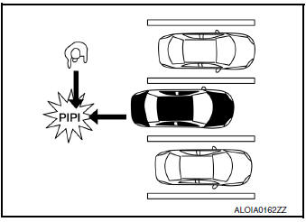
- The MOD system uses the rear view camera to detect approaching moving objects from either side.
- The MOD system can detect moving objects on either side as close as rear obstacles of up to approximately 10 feet (3 m).
MOVING OBJECT DETECTION SYSTEM OPERATION DESCRIPTION
- Around view monitor control unit enables Moving Object Detection system.
- Combination meter turns Moving Object Detection ON indicator lamp ON/OFF according to the signals from around view monitor control unit via CAN communication.
- Around view monitor control unit starts the control as follows, based on a vehicle detection signal.
Operation Condition of Moving Object Detection System
Around view monitor control unit performs the control when the following conditions are satisfied:
- Moving Object Detection ON indicator: ON
- When the vehicle is moving in R (reverse) at 5 MPH (8 km/h) or less.
NOTE:
- When the Moving Object Detection system setting on the Vehicle Information Display is ON.
- Moving Object Detection braking will not operate or will stop operating and only a warning chime will sound under the following conditions:
- When driving with a tire that is not within normal tire conditions (pressure, wear, chain, spare, etc.)
- When the vehicle is equipped with non-original brake parts or suspension parts.
- Do not use the MOD system when towing a trailer.
- Excessive noise such as the audio system will interfere with the chime sound, and it may not be heard.
FCW
FCW : System Description
SYSTEM DIAGRAM
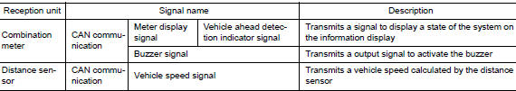
AROUND VIEW MONITOR CONTROL UNIT INPUT/OUTPUT SIGNAL ITEM
Input Signal Item
Output Signal Item
DESCRIPTION
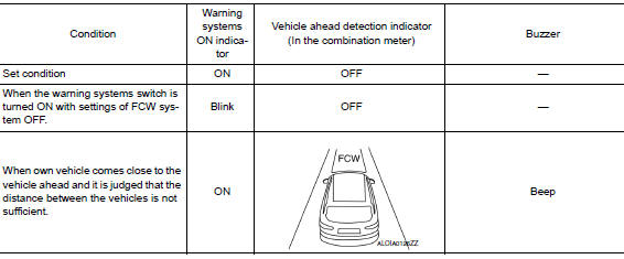
- The Forward Collision Warning (FCW) System alerts the driver by a warning lamp (vehicle ahead detection indicator) and chime when own vehicle is getting close to the vehicle ahead in the traveling lane.
- The FCW system will function when own vehicle is driven at speeds of approximately 10 MPH (15 km/h) and above.
FUNCTION DESCRIPTION
The distance from the vehicle ahead and a relative speed are calculated by using the distance sensor signal transmitted to the combination meter via CAN communication. When judging the necessity of warning from the received distance sensor signal, the distance sensor transmits a buzzer signal and warning signal to the combination meter via CAN communication.
FCW Operating Condition
- Warning system switch ON)
- Vehicle speed: Approximately 10 MPH (15 km/h) and above.
OPERATION
BSW
BSW : Switch Name and Function

|
No. |
Name |
Function |
|
1 |
Warning systems switch | Turns BSW system ON/OFF (When the setting of BSW system on the vehicle information display setting screen is ON) |
BSW : System Display and Warning
INDICATOR AND WARNING LAMP
|
No. |
Name |
Function |
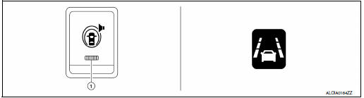
| 1 | Warning systems ON indicator | Indicates that the LDW system is ON. |
| 2 | Blind Spot Warning lamp (orange) |
|
DISPLAY AND WARNING OPERATION
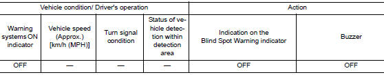
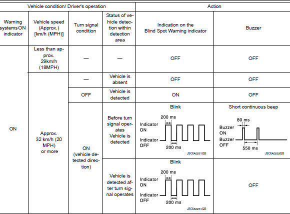
NOTE:
- If vehicle speed exceeds approximately 32 km/h (20 MPH), BSW function operates until the vehicle speed becomes lower than approximately 29 km/h (18 MPH).
- Time shown in the figure is approximate.
- Whenever Blind Spot Warning system is turned off, the warning systems ON indicator remains OFF.
LDW
LDW : Switch Name and Function

|
No. |
Switch name |
Description |
|
1 |
Warning systems switch | Turns LDW system ON/OFF (When the setting of LDW system on the vehicle information display setting screen is ON) |
LDW : Menu Displayed by Pressing Each Switch
INDICATOR LAMP AND WARNING LAMP
|
No. |
Switch name |
Description |
| 1 | Warning systems ON indicator | Indicates that the LDW system is ON |
| 2 | Lane departure warning lamp |
|
DISPLAY AND WARNING
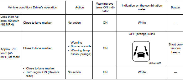
NOTE: After the operating conditions of warning are satisfied, the warning continues until the vehicle speed reaches approximately 60 km/h (40 MPH). Refer to DAS-16, "LDW : System Description".
MOD
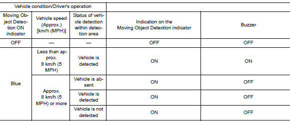
MOD : System Display and Warning
|
No. |
Switch name |
Description |
|
1 |
MOD indicator (blue) |
|
| MOD warning lamp (orange) |
|
DISPLAY AND WARNING OPERATION
FCW
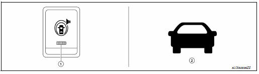
FCW : Switch Name and Function
|
No. |
Switch name |
Description |
| 1 | Warning systems switch | Turns FCW system ON/OFF (When the setting of FCW system in the vehicle information display is ON) |
| 2 | FCW system setting screen (the vehicle information display) | The setting of FCW system can be switched between ON and OFF |
FCW : Menu Displayed by Pressing Each Switch
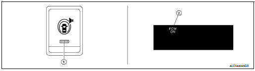
DISPLAY AND WARNING LAMP
|
No. |
Switch name |
Description |
| 1 | Warning systems ON indicator | Indicates that the FCW system is ON. |
| 2 | Vehicle ahead detection indicator | Vehicle ahead detection indicator blinks when the FCW system is activated. |
SYSTEM CONTROL CONDITION DISPLAY
HANDLING PRECAUTION
Precautions for Forward Collision Warning
- The forward collision warning system is designed to warn the driver
before a collision but will not avoid a collision.
It is the driver's responsibility to stay alert, drive safely and be in control of the vehicle at all times.
- The distance sensor does not detect the following objects.
- Pedestrians, animals, or obstacles in the roadway.
- Oncoming vehicles
- Crossing vehicles
- The forward collision warning system does not function when a vehicle ahead is a narrow vehicle, such as a motorcycle.
- The distance sensor may not detect a vehicle ahead in the following conditions:
- Snow or heavy rain
- Dirt, ice, snow or other material covering the radar sensor
- Interference by other radar sources
- Snow or road spray from traveling vehicles is splashed
- Driving in a tunnel
- When the distance to the vehicle ahead is too close, the beam of the radar sensor is obstructed.
- The distance sensor may not detect a second vehicle when driving on a steep downhill slope or on roads with sharp curves.
- Excessive noise will interfere with the warning tone sound, and it may not be heard.
Precautions for Lane Departure Warning
REAR VIEW CAMERA HANDLING
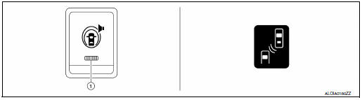
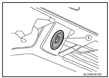
The rear camera unit “1” for the LDW/BSW systems is located above the rear license plate.
To keep the proper operation of the LDW systems and prevent a system malfunction, be sure to observe the following:
- Always keep the camera lens clean. Be careful not to damage the nozzle of the automatic washer and blower.
- Do not attach ”license plate accessories” that reflect light.
- Do not strike or damage the areas around the camera unit.
LANE DEPARTURE WARNING (LDW)
- LDW system is only a warning device to inform the driver of a potential unintended lane departure. It will not steer the vehicle or prevent loss of control. It is the driver’s responsibility to stay alert, drive safely, keep the vehicle in the traveling lane, and be in control of the vehicle at all times.
- The camera unit may not detect properly under the following conditions:
- When towing a trailer.
- When strong light enters the camera unit. (For example, direct sunlight or headlight from the rear.)
- When ambient light changes instantly. (For example, when the vehicle enters or exits a tunnel or passes under a bridge.)
- Automatic washer and blower may not be able to secure detection capability when excessive dirt adheres on the camera lens.
- Excessive noise (e.g. audio system volume, open vehicle window) will interfere with the chime sound, and it may not be heard.
- The camera unit may not be able to detect properly under the following conditions:
- On roads where there are multiple parallel lane markers; lane markers that are faded or not painted clearly; yellow painted lane markers; non-standard lane markers; or lane markers covered with water, dirt or snow, etc.
- On roads where the discontinued lane markers are still detectable.
- On roads where there are sharp curves.
- On roads where there are sharply contrasting objects, such as shadows, snow, water, wheel ruts, seams or lines remaining after road repairs. (The LDW system could detect these items as lane markers.)
- On roads where the traveling lane merges or separates.
- When the vehicle's traveling direction does not align with the lane marker.
- When the road surface is very dark due to scarce ambient light or impaired tail lamp.
- When driving on a curved road, warning will be late on the outside of the curve due to the nature of the system.
Precautions for Blind Spot Warning
REAR VIEW CAMERA HANDLING
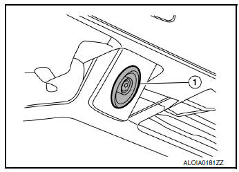
The rear camera unit (1) for the LDW/BSW systems is located above the rear license plate.
To keep the proper operation of the LDW systems and prevent a system malfunction, be sure to observe the following:
- Always keep the camera lens clean. Be careful not to damage the nozzle of the automatic washer and blower.
- Do not attach ”license plate accessories” that reflect light.
- Do not strike or damage the areas around the camera unit.
BLIND SPOT WARNING (BSW)
- BSW system is not a replacement for proper driving procedure and is not designed to prevent contact with vehicles or objects. When changing lanes, always use the side and rear mirrors and turn and look in the direction you will move to ensure it is safe to change lanes. Never rely solely on the BSW system.
- The camera unit may not detect properly under the following conditions:
- When towing a trailer.
- When strong light enters the camera unit. (For example, direct sunlight or headlight from the rear.)
- When ambient light changes instantly. (For example, when the vehicle enters or exits a tunnel or passes under a bridge.)
- Automatic washer and blower may not be able to secure detection capability when excessive dirt adheres on the camera lens.
- Excessive noise (e.g. audio system volume, open vehicle window) will interfere with the chime sound, and it may not be heard.
- The camera unit may not be able to detect when certain objects are present such as:
- Pedestrians, bicycles, animals.
- Several types of vehicles such as motorcycles.
- Oncoming vehicles.
- A vehicle approaching rapidly from behind
- A vehicle which your vehicle overtakes rapidly.
- The camera unit may not be able to detect properly when your vehicle travels beside the middle section of a vehicle with a long wheelbase (e.g., trailer truck, semi-trailer, tractor).
- The camera unit is designed to ignore most stationary objects, however objects such as guardrails, walls, foliage and parked vehicles may occasionally be detected. This is a normal operating condition.
- The camera unit may detect reflection image of vehicles or roadside objects that are not actually in the detection zone, especially when the road is wet.
Precautions for Moving Objects Detection
REAR VIEW CAMERA HANDLING
- The rear view camera is located on the back door.
- Always keep the rear view camera lens clean.
- Do not attach a sticker (including transparent material), install an accessory or paint work over the camera lens.
- Do not strike or scratch the lens causing physical damage to the camera or the surrounding area.
MOVING OBJECT DETECTION
- The Moving Object Detection system is not a replacement for proper driving procedure and is not designed to prevent contact with vehicles or objects. When backing up, always look in the direction driver will move to ensure it is safe to proceed. Never rely solely on the Moving Object Detection system.
- Using the Moving Object Detection system under some road or weather conditions could lead to improper system operation. Always rely on driver's own steering and braking operation to avoid accidents.
- The Moving Object Detection system may not provide a warning for vehicles that pass through the detection zone quickly.
- Do not use the Moving Object Detection system when towing a trailer.
- Excessive noise (e.g., audio system volume, open vehicle window) will interfere with the chime sound, and it may not be heard.
- The rear view camera may not be able to detect and activate Moving Object Detection when certain objects are present such as:
- Pedestrians, bicycles, animals.
- A vehicle passing at a speed greater than approximately 15 MPH (24km/h).
- Severe weather or road spray conditions may reduce the ability of the radar to detect other vehicles.
- Do not use the MOD system under the following conditions because the system may not function properly:
- When driving with a tire that is not within normal tire condition (example: tire wear, low pressure, spare tire, chain, non-standard wheels).
- When the vehicle is equipped with non-original brake parts or suspension parts.
DIAGNOSIS SYSTEM (AROUND VIEW MONITOR CONTROL UNIT)
CONSULT Function
CONSULT FUNCTIONS
CONSULT performs the following functions via communication with the around view monitor control unit.
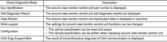
ECU IDENTIFICATION
The part number of around view monitor control unit is displayed.
SELF DIAGNOSTIC RESULT
Refer to DAS-47, "DTC Index".
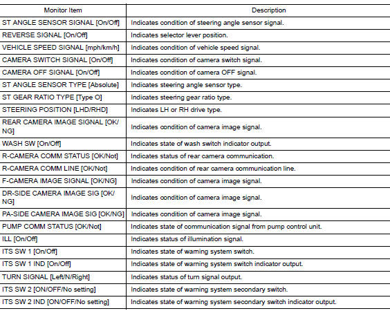
DATA MONITOR
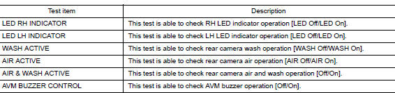
ACTIVE TEST
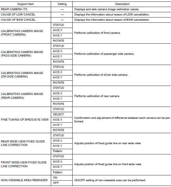
WORK SUPPORT
CONFIGURATION
Refer to AV-289, "CONFIGURATION (AV CONTROL UNIT) : Description".
CAN DIAG SUPPORT MNTR
Refer to LAN-14, "CAN Diagnostic Support Monitor".
DIAGNOSIS SYSTEM (DISTANCE SENSOR)
CONSULT Function (LASER/RADAR)
APPLICATION ITEMS
CONSULT performs the following functions via CAN communication with Distance sensor.
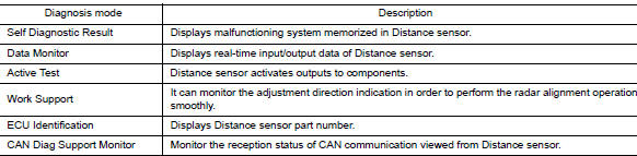
SELF DIAGNOSTIC RESULT
Refer to DAS-49, "DTC Index".
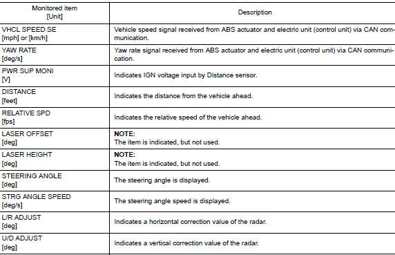
DATA MONITOR
NOTE: The following table includes information (items) inapplicable to this vehicle. For information (items) applicable to this vehicle, refer to CONSULT display items.
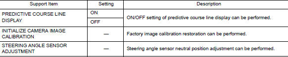
WORK SUPPORT

Distance sensor alignment
Refer to DAS-72, "Description".
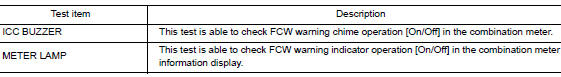
ACTIVE TEST
 Preparation
Special Service Tool
The actual shape of the tools may differ from those illustrated here.
Tool number
(TechMate No.)
Tool name
Description
—
(J-46534)
Trim ...
 ECU diagnosis information
AROUND VIEW MONITOR CONTROL UNIT
Reference Value
VALUES ON THE DIAGNOSIS TOOL
TERMINAL LAYOUT
PHYSICAL VALUES
DTC Index
DISTANCE SENSOR
Reference Value
VALUES ON THE ...
Other materials:
The braking distance is long
Description
Brake stopping distance is long when ABS function is operated.
Diagnosis Procedure
CAUTION:
Brake stopping distance on slippery road like rough road, gravel road or snowy
road may become
longer when ABS is operated than when ABS is not operated
1.CHECK BRAKING FORCE
Check brake ...
Exterior front
Front view camera (if so equipped)
Engine hood
Windshield wiper and washer switch, wiper blades
Windshield-washer fluid
Windshield
Power windows
Door locks, NISSAN Intelligent Key® (if so equipped), NISSAN Jackknife
key (if so equipped), key ...
Symptom diagnosis
SQUEAK AND RATTLE TROUBLE DIAGNOSES
Work Flow
CUSTOMER INTERVIEW
Interview the customer if possible, to determine the conditions that exist
when the noise occurs. Use the Diagnostic
Worksheet during the interview to document the facts and conditions when the
noise occurs and any
custome ...
