Nissan Rogue Service Manual: System description
COMPONENT PARTS
Component Parts Location
|
No. |
Component |
Description |
| 1 | Push-button ignition switch1 | Push-button ignition switch (push switch) is pressed (ON), and transmits status signal to BCM and IPDM E/R. |
| Ignition switch2 | Ignition switch is turned to ON, and transmits status signal to BCM and IPDM E/R. | |
| 2 | IPDM E/R |
|
| 3 | BCM |
|
| 4 | Ignition relay-2 (in fuse block) |
|
| 5 | Front blower motor relay (in fuse block) |
|
| 6 | Accessory relay-1 (in fuse block) |
|
1: With Intelligent Key system
2: With remote keyless entry system
SYSTEM
POWER DISTRIBUTION SYSTEM
POWER DISTRIBUTION SYSTEM : System Description
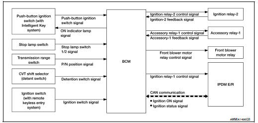
SYSTEM DIAGRAM
SYSTEM DESCRIPTION
With Intelligent Key System
- PDS (POWER DISTRIBUTION SYSTEM) is the system that the BCM controls with the operation of the push-button ignition switch to perform the power distribution to each power circuit. This system is used instead of the mechanical power supply changing mechanism with the operation of the conventional key cylinder.
- The push-button ignition switch can be operated when Intelligent Key is in the following conditions:
- Intelligent Key is in the detection area of the inside key antenna.
- Intelligent Key backside is contacted to push-button ignition switch.
- The push-button ignition switch operation is input to BCM as a signal. BCM changes the power supply position according to the status and operates the following relays to supply power to each power circuit.
- Ignition relay-1
- Ignition relay-2
- Accessory relay-1
- Front blower motor relay
NOTE: The engine switch operation changes due to the conditions of brake pedal, selector lever and vehicle speed.
- The power supply position can be confirmed with the lighting of the indicator in the push-button ignition switch.
With Remote Keyless Entry System
- PDS (POWER DISTRIBUTION SYSTEM) is the system that the BCM controls with the operation of the ignition switch to perform the power distribution to each power circuit.
- The ignition switch operation is input to the BCM as a signal. BCM changes the power supply position according to the status and operates the following relays to supply power to each power circuit:
- Ignition relay-1
- Ignition relay-2
- Accessory relay-1
- Front blower motor relay
IGNITION BATTERY SAVER SYSTEM
When all the following conditions are met for 30 minutes, the ignition battery saver system will cut off the power supply to prevent battery discharge.
- The ignition is in the ON position
- All doors are closed
- Selector lever is in the P (park) position
Reset Condition of Ignition Battery Saver System
In order to prevent the battery from discharging, the ignition battery saver system will cut off the power supply when all doors are closed, the selector lever is in P (park) position and the ignition is left in the ON position for 30 minutes.
- Opening any door
- Operating door request switch on door handle
- Operating Intelligent Key (with Intelligent Key system)
- Operating keyfob (with remote keyless entry system)
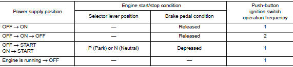
POWER SUPPLY POSITION CHANGE TABLE BY PUSH-BUTTON IGNITION SWITCH OPERATION (WITH INTELLIGENT KEY SYSTEM)
The power supply position changing operation can be performed with the following operations.
NOTE:
- When an Intelligent Key is within the detection area of inside key antenna and when Intelligent Key backside is contacted to push-button ignition switch, it is equivalent to the operations below.
- When starting the engine, the BCM monitors under the engine start conditions:
- Brake pedal operating condition
- Selector lever position
- Vehicle speed
Vehicle speed: less than 4 km/h (2.5 MPH)
Vehicle speed: 4 km/h (2.5 MPH) or more
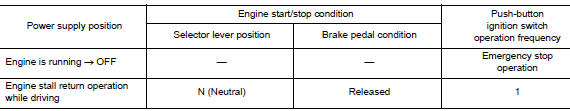
Emergency stop operation
- Press and hold the push-button ignition switch for 2 seconds or more.
- Press the push-button ignition switch 3 times or more within 1.5 seconds.
WITH INTELLIGENT KEY
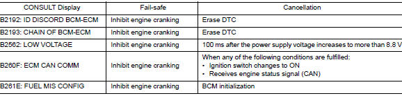
WITH INTELLIGENT KEY : Fail Safe
WITHOUT INTELLIGENT KEY
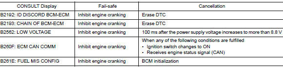
WITHOUT INTELLIGENT KEY : Fail Safe
DIAGNOSIS SYSTEM (BCM) (WITH INTELLIGENT KEY SYSTEM)
COMMON ITEM
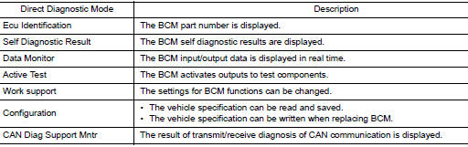
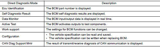
COMMON ITEM : CONSULT Function (BCM - COMMON ITEM)
APPLICATION ITEM
CONSULT performs the following functions via CAN communication with BCM.
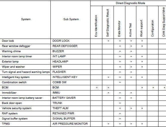
SYSTEM APPLICATION
BCM can perform the following functions.
INTELLIGENT KEY
INTELLIGENT KEY : CONSULT Function (BCM - INTELLIGENT KEY)
SELF DIAGNOSTIC RESULT
Refer to BCS-48, "DTC Index".
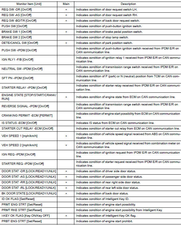
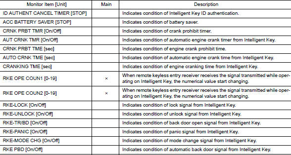
DATA MONITOR
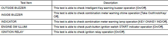
ACTIVE TEST
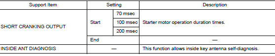
WORK SUPPORT
DIAGNOSIS SYSTEM (BCM) (WITHOUT INTELLIGENT KEY SYSTEM)
COMMON ITEM
COMMON ITEM : CONSULT Function (BCM - COMMON ITEM)
APPLICATION ITEM
CONSULT performs the following functions via CAN communication with BCM.
SYSTEM APPLICATION
BCM can perform the following functions.

MULTI REMOTE ENT
MULTI REMOTE ENT : CONSULT Function (BCM - MULTI REMOTE ENT)
WORK SUPPORT

 Precaution
Precaution for Supplemental Restraint System (SRS) "AIR BAG" and "SEAT
BELT
PRE-TENSIONER"
The Supplemental Restraint System such as “AIR BAG” and “SEAT BELT PRE-TENSIONE ...
 ECU diagnosis information
BCM
List of ECU Reference
...
Other materials:
CAN system (type 2)
MAIN LINE BETWEEN IPDM-E AND DLC CIRCUIT
Diagnosis Procedure
1.CHECK CONNECTOR
Turn the ignition switch OFF.
Disconnect the battery cable from the negative terminal.
Check the following terminals and connectors for damage, bend and
loose connection (connector side
an ...
Precaution
Precaution for supplemental restraint system (srs) "air bag" and "seat
belt
pre-tensioner"
The Supplemental Restraint System such as “AIR BAG” and “SEAT BELT
PRE-TENSIONER”, used along
with a front seat belt, helps to reduce the risk or severity of injury to the
...
Driver air bag module
Exploded View
Steering wheel
Driver air bag module
Removal and Installation
WARNING:
Before servicing the SRS, turn ignition switch OFF, disconnect
both battery terminals then wait at
least three minutes.
Always work from the side of driver air bag module. Do no ...
