Nissan Rogue Service Manual: System description
COMPONENT PARTS
Component Parts Location
- Right rear wheel area
- Instrument panel
- Engine compartment
- Left side of instrument panel (view with trim panel removed)
|
No. |
Part |
Function |
| 1 | Optical sensor | Refer to EXL-10, "Optical Sensor". |
| 2 | LED headlamp control module | Turns the headlamps ON according to the power supply from IPDM E/R. |
| 3 | Headlamp aiming motor | Moves the headlamps up/down based on inputs from the front and rear height sensors. |
| 4 | Front height sensor | Sends the vehicles pitch angle signal to the IPDM E/R necessary for adjusting the headlamp aiming motors. |
| 5 | Rear height sensor | Sends the vehicles pitch angle signal to the IPDM E/R necessary for adjusting the headlamp aiming motors. |
| 6 | Combination switch (Lighting and turn signal switch) | Refer to BCS-9, "COMBINATION SWITCH READING SYSTEM : System Description" (with Intelligent Key) or BCS-81, "COMBINATION SWITCH READING SYSTEM : System Description" (without Intelligent Key). |
| 7 | Hazard switch | Refer to EXL-11, "Hazard Switch". |
| 8 | IPDM E/R |
|
| 9 | BCM |
|
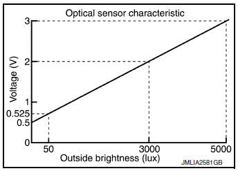
Optical Sensor
Optical sensor converts the outside brightness (lux) to voltage and transmits the optical sensor signal to BCM.
Hazard Switch
Inputs the hazard switch ON/OFF signal to BCM.
SYSTEM
HEADLAMP SYSTEM
HEADLAMP SYSTEM : System Description
SYSTEM DIAGRAM
OUTLINE
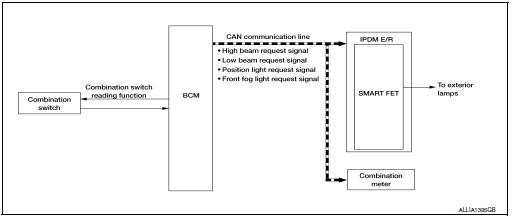
Headlamp is controlled by combination switch reading function and headlamp control function of BCM, and Smart FET control function of IPDM E/R.
HEADLAMP (LO) OPERATION
- BCM detects the combination switch condition with the combination switch reading function.
- BCM transmits the low beam request signal to IPDM E/R with CAN communication according to the headlamp (LO) ON condition.
Headlamp (LO) ON condition
- Lighting switch 2ND
- Lighting switch AUTO (auto light function ON judgment)
- Lighting switch AUTO, with the front fog lamp switch ON and the power switch ON
- Lighting switch PASS
HEADLAMP (HI) OPERATION
- BCM transmits the high beam request signal to IPDM E/R and the combination meter with CAN communication according to the headlamp (HI) ON condition.
Headlamp (HI) ON condition:
- Lighting switch HI with the lighting switch 2ND or AUTO (auto light function ON judgment)
- Lighting switch PASS
- Lighting switch AUTO, with the front fog lamp switch ON, the power switch ON and lighting switch HI
- Combination meter turns the high beam indicator lamp ON according to the high beam request signal.
- IPDM E/R turns the headlamp ON according to the high beam request signal.
HEADLAMP SYSTEM : Fail-Safe
CAN COMMUNICATION CONTROL
When CAN communication with BCM is impossible, IPDM E/R performs fail-safe control. After CAN communication recovers normally, it also returns to normal control.
If no CAN communication is available with BCM
|
Control part |
Fail-safe operation |
| Headlamp |
|
AUTO LIGHT SYSTEM
AUTO LIGHT SYSTEM : System Description
SYSTEM DIAGRAM
OUTLINE
- Auto light system is controlled by each function of BCM and IPDM E/R.
Controlled by BCM:
- Combination switch reading function
- Headlamp control function
- Auto light function
- Delay timer function
- Auto light adjustment system
Controlled by IPDM E/R:
- Auto light system has the auto light function and delay timer function.
- Auto light function automatically turns ON/OFF the exterior lamps* and each illumination automatically, depending on the outside brightness.
- When auto light system turns the exterior lamps ON with the power switch OFF, delay timer function turns the exterior lamps OFF, depending on the vehicle condition with the auto light function after a certain period of time.
*: Headlamp (LO/HI), parking lamp, side marker lamp, tail lamp and front fog lamp (Headlamp HI and front fog lamp depend on the combination switch condition).
AUTO LIGHT FUNCTION
- BCM detects the combination switch condition with the combination switch reading function.
- BCM supplies voltage to optical sensor when the power switch is turned ON or ACC.
- Optical sensor converts outside brightness (lux) to voltage and transmits the optical sensor signal to BCM.
- BCM judges outside brightness from the optical sensor signal and judges ON/OFF condition of the exterior lamp and each illumination according to the outside brightness.
- BCM transmits each request signal to IPDM E/R and combination meter via CAN communication according to ON/OFF condition by the auto light function.
NOTE: ON/OFF timing differs based on the sensitivity from the setting. The setting can be set by CONSULT. Refer to.
AUTO LIGHT ADJUSTMENT SYSTEM
The auto light adjustment system automatically, dims/brightens the display, according to brightness outside the vehicle, when lighting switch 1ST, lighting switch 2ND or lighting switch AUTO is operated. Refer to EXL- 13, "AUTO LIGHT SYSTEM : System Description".
DELAY TIMER FUNCTION
BCM turns the exterior lamp OFF depending on the vehicle condition with the auto light function when the power switch is turned OFF.
- Turns the exterior lamp OFF 5 minutes after detecting that any door opens. (Door switch ON).
- Turns the exterior lamp OFF a certain period of time* after closing all doors. (Door switch ONтЖТOFF).
- Turns the exterior lamp OFF with the power switch ACC or the light switch OFF.
*: The preset time is 45 seconds. The timer operating time can be set by CONSULT. Refer to BCS-19, "HEADLAMP : CONSULT Function (BCM - HEADLAMP)" (with Intelligent Key) or BCS-90, "HEADLAMP : CONSULT Function (BCM - HEADLAMP)" (without Intelligent Key).
NOTE: When any position other than the light switch AUTO is set, the auto light system function switches to the exterior lamp battery saver function.
DAYTIME RUNNING LIGHT SYSTEM
DAYTIME RUNNING LIGHT SYSTEM : System Description
SYSTEM DIAGRAM
OUTLINE
- Daytime running light is controlled by daytime running light control function and combination switch reading function of BCM, and smart FET of IPDM E/R.
DAYTIME RUNNING LIGHT OPERATION
- BCM detects the combination switch condition by the combination switch reading function.
- BCM detects the vehicle condition according to power switch
- BCM detects the parking brake condition by the parking brake switch signal received from combination meter using CAN communication.
- BCM transmits the daytime running light request signal to IPDM E/R using CAN communication according to the daytime running light ON condition.
Daytime running light ON condition:
- Vehicle condition READY
- Lighting switch OFF or 1ST
- Lighting switch AUTO, and the auto light function OFF judgment
- Parking brake switch OFF
- IPDM E/R controls the daytime running light request signal.
- Power is supplied from the IPDM E/R to the daytime lights.
TURN SIGNAL AND HAZARD WARNING LAMP SYSTEM
TURN SIGNAL AND HAZARD WARNING LAMP SYSTEM : System Description
SYSTEM DIAGRAM
OUTLINE
Turn signal lamp and the hazard warning lamp is controlled by combination switch reading function and the flasher control function of BCM.
TURN SIGNAL LAMP OPERATION
- BCM detects the combination switch condition by the combination switch reading function.
- BCM supplies voltage to the right (left) turn signal lamp circuit when the power switch is ON and the turn signal switch is in the right (left) position. BCM blinks the turn signal lamp.
HAZARD WARNING LAMP OPERATION
BCM supplies voltage to both turn signal lamp circuit when the hazard switch is ON. BCM blinks the hazard warning lamp.
TURN SIGNAL INDICATOR LAMP AND TURN SIGNAL OPERATION
- BCM transmits the turn signal indicator lamp signal to the combination meter using CAN communication while the turn signal lamp and the hazard warning lamp are operating.
- Combination meter outputs the turn signal sound with the integrated buzzer while blinking the turn signal indicator lamp according to the turn signal indicator lamp signal.
HIGH FLASHER OPERATION
- BCM detects the turn signal lamp circuit status from the current value.
- BCM increases the turn signal lamp blinking speed if the bulb or harness open is detected with the turn signal lamp operating.
NOTE: The blinking speed is normal while operating the hazard warning lamp.
PARKING, LICENSE PLATE, SIDE MARKER AND TAIL LAMP SYSTEM
PARKING, LICENSE PLATE, SIDE MARKER AND TAIL LAMP SYSTEM : System Description
SYSTEM DIAGRAM
OUTLINE
Parking, license plate, side marker and tail lamps are controlled by combination switch reading function and headlamp control function of BCM, and smart FET of IPDM E/R.
PARKING, LICENSE PLATE, SIDE MARKER AND TAIL LAMPS OPERATION
- BCM detects the combination switch condition by the combination switch reading function.
- BCM transmits the position light request signal to IPDM E/R and the combination meter via CAN communication according to the ON/OFF condition of the parking, license plate, side marker and tail lamps.
Parking, license plate, side marker and tail lamps ON condition:
- Lighting switch 1ST
- Lighting switch 2ND
- Lighting switch AUTO, and the auto light function ON judgment
- Lighting switch AUTO, with the front fog lamp switch ON and the power switch ON
- IPDM E/R turns the parking, license plate, side marker and tail lamps ON according to the position light request signal.
- Combination meter turns the tail lamp indicator lamp ON according to the position light request signal.
PARKING, LICENSE PLATE, SIDE MARKER AND TAIL LAMP SYSTEM : Fail-Safe
CAN COMMUNICATION CONTROL
When CAN communication with BCM is impossible, IPDM E/R performs fail-safe control. After CAN communication recovers normally, it also returns to normal control.
If no CAN communication is available with BCM
|
Control part |
Fail-safe operation |
|
|
FRONT FOG LAMP SYSTEM
FRONT FOG LAMP SYSTEM : System Description
SYSTEM DIAGRAM
OUTLINE
Front fog lamp is controlled by combination switch reading function, front fog lamp control function of BCM, and smart FET function of IPDM E/R.
FRONT FOG LAMP OPERATION
- BCM detects the combination switch condition by the combination switch reading function.
- BCM transmits the front fog lights request signal to IPDM E/R and the combination meter via CAN communication according to the front fog lamp ON condition.
Front fog lamp ON condition:
- Front fog lamp switch ON, and any of the following condition is satisfied (except for the high beam ON).
- Lighting switch 2ND
- Lighting switch AUTO and the power switch ON
IPDM E/R turns the front fog lamp ON according to the front fog lights request signal.
Combination meter turns the front fog lamp indicator lamp ON according to the front fog lights request signal.
FRONT FOG LAMP SYSTEM : Fail-Safe
CAN COMMUNICATION CONTROL
When CAN communication with BCM is impossible, IPDM E/R performs fail-safe control. After CAN communication recovers normally, it also returns to normal control.
If no CAN communication is available with BCM
|
Control part |
Fail-safe operation |
| Front fog lamp | Front fog lamp OFF |
EXTERIOR LAMP BATTERY SAVER SYSTEM
EXTERIOR LAMP BATTERY SAVER SYSTEM : System Description
SYSTEM DIAGRAM
OUTLINE
- Exterior lamp battery saver system is controlled by each function of BCM and IPDM E/R.
Controlled by BCM:
- Combination switch reading function
- Headlamp control function
- Exterior lamp battery saver function
Controlled by IPDM E/R:
- BCM turns the exterior lamps* OFF after a period of time to prevent the battery from over-discharge when the power switch is turned OFF with the exterior lamps ON.
*: Headlamp (LO/HI), parking lamp, tail lamp, side marker lamp, license plate lamp and front fog lamp
EXTERIOR LAMP BATTERY SAVER ACTIVATION
BCM activates the timer and turns the exterior lamp OFF 5 minutes after the power switch is turned from ON тЖТ OFF with the exterior lamps ON.
NOTE:
- Headlamp control function turns the exterior lamps ON normally when the power switch is turned ACC or set the vehicle to READY (both before and after the exterior lamp battery saver is turned OFF).
- The timer starts at the time that the lighting switch is turned from OFF тЖТ 1ST or 2ND with the exterior lamps OFF.
DIAGNOSIS SYSTEM (BCM)
WITH INTELLIGENT KEY
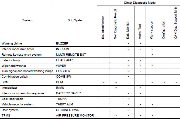
WITH INTELLIGENT KEY : CONSULT Function (BCM - COMMON ITEM)
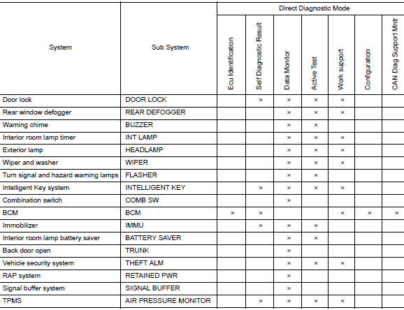
APPLICATION ITEM
CONSULT performs the following functions via CAN communication with BCM.
|
Direct Diagnostic Mode |
Description |
| Ecu Identification | The BCM part number is displayed |
| Self Diagnostic Result | The BCM self diagnostic results are displayed. |
| Data Monitor | The BCM input/output data is displayed in real time. |
| Active Test | The BCM activates outputs to test components. |
| Work support | The settings for BCM functions can be changed. |
| Configuration |
|
| CAN Diag Support Mntr | The result of transmit/receive diagnosis of CAN communication is displayed. |
SYSTEM APPLICATION
BCM can perform the following functions.
WITH INTELLIGENT KEY : CONSULT Function (BCM - HEADLAMP)
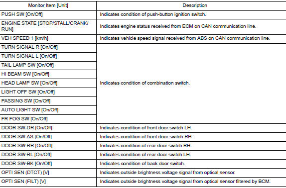
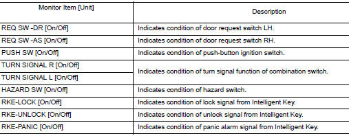
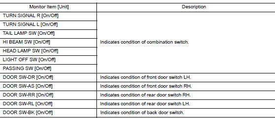
DATA MONITOR
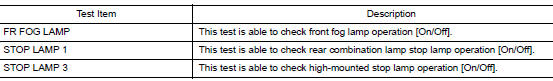
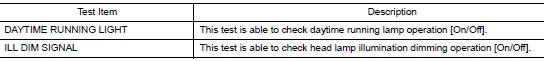
ACTIVE TEST
WORK SUPPORT
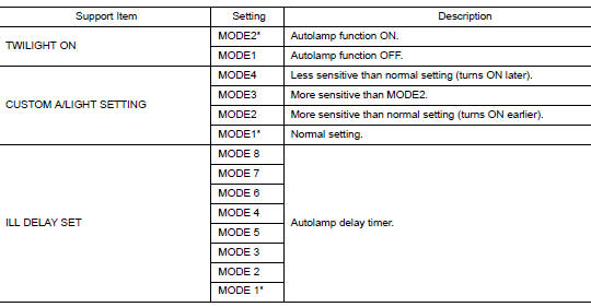
*: Initial setting
WITH INTELLIGENT KEY : CONSULT Function (BCM - FLASHER)
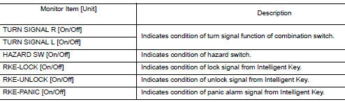
DATA MONITOR
ACTIVE TEST

WITHOUT INTELLIGENT KEY
WITHOUT INTELLIGENT KEY : CONSULT Function (BCM - COMMON ITEM)
APPLICATION ITEM
CONSULT performs the following functions via CAN communication with BCM.
|
Direct Diagnostic Mode |
Description |
| Ecu Identification | The BCM part number is displayed. |
| Self Diagnostic Result | The BCM self diagnostic results are displayed. |
| Data Monitor | The BCM input/output data is displayed in real time. |
| Active Test | The BCM activates outputs to test components. |
| Work support | The settings for BCM functions can be changed. |
| Configuration |
|
| CAN Diag Support Mntr | The result of transmit/receive diagnosis of CAN communication is displayed. |
SYSTEM APPLICATION
BCM can perform the following functions.
WITHOUT INTELLIGENT KEY : CONSULT Function (BCM - HEADLAMP)
DATA MONITOR
ACTIVE TEST
WITHOUT INTELLIGENT KEY : CONSULT Function (BCM - FLASHER)
DATA MONITOR
ACTIVE TEST

DIAGNOSIS SYSTEM (IPDM E/R)
CONSULT Function (IPDM E/R)
APPLICATION ITEM
CONSULT performs the following functions via CAN communication with IPDM E/R.
|
Direct Diagnostic Mode |
Description |
| Ecu Identification | The IPDM E/R part number is displayed. |
| Self Diagnostic Result | The IPDM E/R self diagnostic results are displayed. |
| Data Monitor | The IPDM E/R input/output data is displayed in real time. |
| Active Test | The IPDM E/R activates outputs to test components. |
| CAN Diag Support Mntr | The result of transmit/receive diagnosis of CAN communication is displayed. |
ECU IDENTIFICATION
The IPDM E/R part number is displayed.
SELF DIAGNOSTIC RESULT
Refer to PCS-20, "DTC Index".
DATA MONITOR
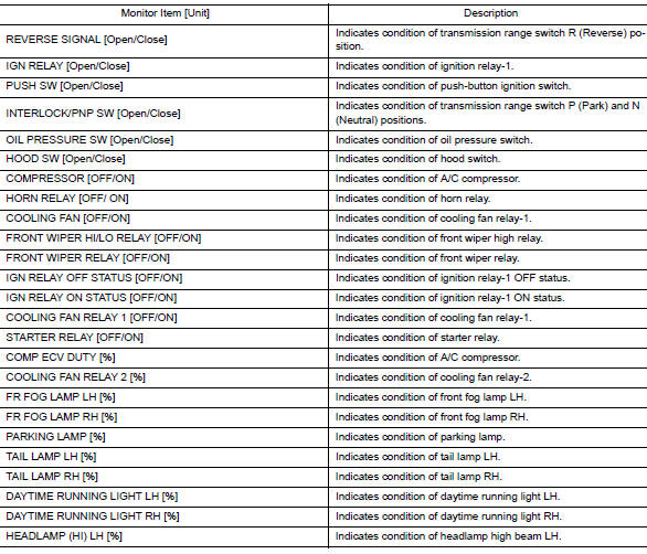
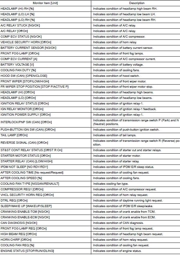
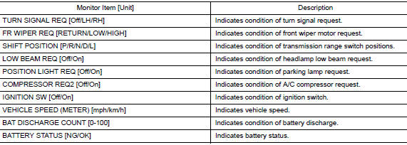
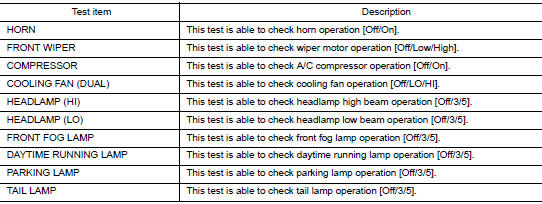
ACTIVE TEST
CAN DIAG SUPPORT MNTR
Refer to LAN-14, "CAN Diagnostic Support Monitor".
 Preparation
Special Service Tool
The actual shape of the tools may differ from those illustrated here.
Tool number
(TechMate No.)
Tool name
Description
тАФ
(J-46534)
Trim ...
 ECU diagnosis information
BCM, IPDM E/R
List of ECU Reference
...
Other materials:
Door switch
WITH INTELLIGENT KEY
WITH INTELLIGENT KEY : Component Function Check
1.CHECK FUNCTION
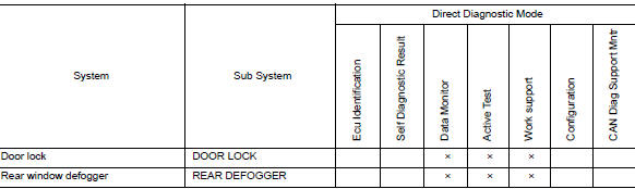
Select "DOOR LOCK" of "BCM" using CONSULT.
Select "DOOR SW-DR", "DOOR SW-AS", "DOOR SW-RL", "DOOR SW-RR", in "Data
Monitor&quo ...
ECU diagnosis information
AUDIO UNIT
Reference Value
TERMINAL LAYOUT
PHYSICAL VALUES
...
P1212 TCS communication line
Description
This CAN communication line is used to control the smooth engine operation
during the TCS operation. Pulse
signals are exchanged between ECM and тАЬABS actuator and electric unit (control
unit)тАЭ.
Be sure to erase the malfunction information such as DTC not only for тАЬABS
ac ...
