Nissan Rogue Service Manual: System description
COMPONENT PARTS
POWER DOOR LOCK SYSTEM
POWER DOOR LOCK SYSTEM : Component Parts Location
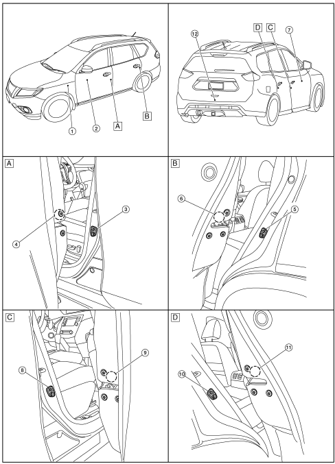
|
No |
Component |
Function |
| 1 | BCM | Controls the door lock system. Refer to BCS-79, "BODY CONTROL SYSTEM : Component Parts Location" for detailed installation location |
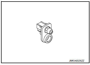
| 2 | Main power window and door lock/unlock switch | DLK-22, "Door Lock and Unlock Switch (Driver Side)" |
| 3 | Front door switch LH | DLK-286, "Front Door Switch" |
| 4 | Front door lock assembly LH | DLK-25, "Front Door Lock Assembly (LH)" |
| 5 | Rear door switch LH | DLK-285, "Rear Door Switch" |
| 6 | Rear door lock actuator LH | Rear door lock actuator locks/unlocks the rear door latch assembly. |
| 7 | Front power window and door lock/unlock switch RH | DLK-22, "Door Lock and Unlock Switch (Passenger Side)" |
| 8 | Front door switch RH | DLK-286, "Front Door Switch" |
| 9 | Front door lock actuator RH | Rear door lock actuator locks/unlocks the rear door latch assembly. |
| 10 | Rear door switch RH | DLK-285, "Rear Door Switch" |
| 11 | Rear door lock actuator RH | Rear door lock actuator locks/unlocks the rear door latch assembly. |
| 12 | Back door lock assembly (door ajar switch) | DLK-21, "Back Door Lock Assembly" |
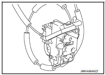
Front Door Lock Assembly (Driver Side)
- Door lock actuator and unlock sensor are Integrated in driver door lock assembly.
- Door lock actuator receives lock/unlock signal from BCM, and then locks/unlocks driver door.
- Only front door lock assembly (driver side) integrates unlock
sensor.
Unlock sensor transmits lock/unlock status of driver seat to BCM.
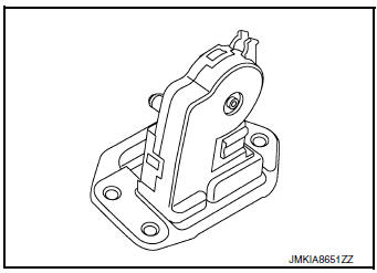
Back Door Lock Assembly
- Back door lock assembly lock assembly integrates door lock actuator and back door latch.
- Door lock actuator locks/unlocks the back door according to the door lock/unlock signal from BCM.
Rear Door Switch
Door switch detects open/close status of door and transmits door switch signal to BCM.
Front Door Switch
Door switch detects open/close status of door and transmits door switch signal to BCM.
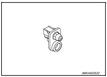
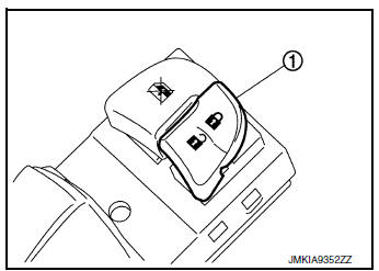
Door Lock and Unlock Switch
- Door lock and unlock switch transmits door lock/unlock signal operation to BCM.
- Door lock and unlock switch (1) is integrated in the power window main switch and front power window switch (passenger side).
SYSTEM
POWER DOOR LOCK SYSTEM
POWER DOOR LOCK SYSTEM : System Diagram
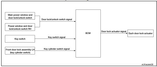
POWER DOOR LOCK SYSTEM : System Description
|
Switch |
Input/output signal to BCM |
BCM function |
Actuator |
| Main power window and door lock/unlock switch | Door lock/unlock signal | Door lock/ k/unlock control | Door lock actuator |
| Power window and door lock/ unlock switch RH | |||
| Front door lock key cylinder switch LH |
DOOR LOCK FUNCTION
Functions Available by Operating the Door Lock and Unlock Switches on Driver Door and Passenger Door
- Interlocked with the locking operation of door lock and unlock switch, door lock actuators of all door lock actuators are locked.
- Interlocked with the unlocking operation of door lock and unlock switch, door lock actuators of all door lock actuators are unlocked.
Functions Available by Operating the Key Cylinder Switch on Driver Door
- Interlocked with the locking operation of door key cylinder, door lock actuators of all door lock actuators are locked.
Selective Unlock Operation
- When door key cylinder is unlocked, door lock actuator driver side is unlocked.
- When door key cylinder is unlocked for the second time within 5
seconds after the first operation, door lock
actuators on all doors are unlocked.
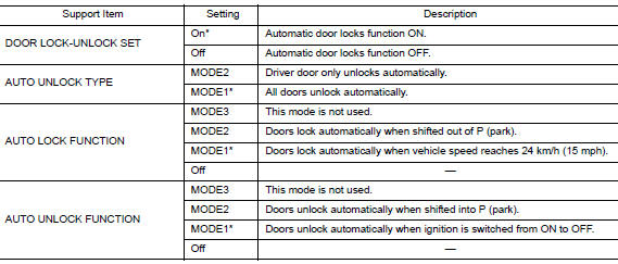
Select unlock operation mode can be changed using DOOR LOCK-UNLOCK SET mode in ŌĆ£WORK SUPPORTŌĆØ.
Refer to BCS-87, "DOOR LOCK : CONSULT Function (BCM - DOOR LOCK)".
REMOTE KEYLESS ENTRY SYSTEM
REMOTE KEYLESS ENTRY SYSTEM : System Diagram
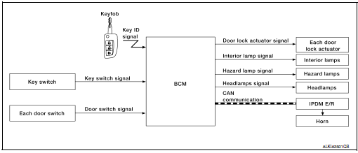
REMOTE KEYLESS ENTRY SYSTEM : System Description
The remote keyless entry system can be locked and unlocked by pressing door lock and unlock button of keyfob.
DOOR LOCK AND UNLOCK OPERATION
- When door lock and unlock button of keyfob is pressed, door lock and unlock signal transmits from keyfob to BCM.
- When BCM receives the door lock and unlock signal, it operates door lock actuator, flashes the hazard lamp (lock: 2 times, unlock: 1 time) and horn chirp signal to IPDM E/R at the same time as a reminder.
- IPDM E/R honks horn (lock: 1 time) as a reminder.
OPERATION CONDITION
|
Remote controller operation |
Operation condition |
| Lock/unlock | Key switch is OFF. Mechanical key is removed from the ignition cylinder. |
OPERATION AREA
To ensure that the keyfob works effectively, use within 10 m (33ft) range of the vehicle, however the operable range may differ according to surroundings.
SELECTIVE UNLOCK OPERATION
When door lock is unlocked, pressing LOCK button on keyfob once will lock all doors. When door lock is locked, pressing UNLOCK button on keyfob will unlock driver side door. Pressing UNLOCK button on keyfob second time within 5 seconds from the first time will unlock all doors.
HAZARD AND HORN REMINDER
When the doors are locked or unlocked by keyfob, power is supplied to sound horn and flash hazard warning lamps as a reminder The hazard and horn reminder has C mode (horn chirp mode) and S mode (non-horn chirp mode).
How to Change Hazard and Horn Reminder Modes
 With CONSULT
Hazard and horn reminders can be changed using "WORK SUPPORT" mode in "MULTI REMOTE ENT".
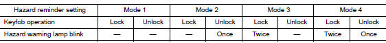

Hazard and horn reminders do not operate if any door switch is ON (any door is OPEN).
Hazard reminder can be changed using ŌĆ£HAZARD LAMP SETŌĆØ mode in ŌĆ£WORK SUPPORTŌĆØ.
Horn reminder can be changed using ŌĆ£HORN CHIRP SETŌĆØ mode in ŌĆ£WORK SUPPORTŌĆØ.
Refer to BCS-90, "MULTI REMOTE ENT : CONSULT Function (BCM - MULTI REMOTE ENT)".
 Without CONSULT
Refer to OwnerŌĆÖs Manual for instructions.
AUTO DOOR LOCK OPERATION
When all doors are locked, ignition switch is OFF and key switch is OFF (mechanical key is removed from the ignition cylinder), doors are unlocked with keyfob button. When BCM does not receive the following signals within 1 minute, all doors are locked.
- Door switch is ON (door is opened)
- Door is locked
- Ignition switch is ON
- Key switch is ON (mechanical key is inserted in the ignition cylinder)
Auto door lock mode can be changed by ŌĆ£AUTO LOCK SETŌĆØ mode in ŌĆ£WORK SUPPORTŌĆØ. Refer to BCS-90, "MULTI REMOTE ENT : CONSULT Function (BCM - MULTI REMOTE ENT)".
PANIC ALARM OPERATION
When key switch is OFF (mechanical key is removed from the ignition cylinder), BCM turns ON and OFF horn and headlamp intermittently with input of PANIC ALARM signal from keyfob.
BCM outputs to headlamps and IPDM E/R for panic alarm signal (horn signal) via CAN communication lines.
The alarm automatically turns OFF after 25 seconds or when BCM receives any signal from keyfob.
Panic alarm operation mode can be changed using ŌĆ£PANIC ALARM SETŌĆØ mode in ŌĆ£WORK SUPPORTŌĆØ.
Refer to BCS-90, "MULTI REMOTE ENT : CONSULT Function (BCM - MULTI REMOTE ENT)".
INTERIOR LAMP TIMER OPERATION
When the following conditions occur, remote keyless entry system turns on interior lamp for 15 seconds with input of UNLOCK signal from keyfob. For detailed description, refer to INL-7, "INTERIOR ROOM LAMP CONTROL SYSTEM : System Description".
- Interior room lamp switch is in the DOOR position
- Door switch OFF (when all the doors are closed).
DIAGNOSIS SYSTEM (BCM)
COMMON ITEM
COMMON ITEM : CONSULT Function (BCM - COMMON ITEM
APPLICATION ITEM
CONSULT performs the following functions via CAN communication with BCM.
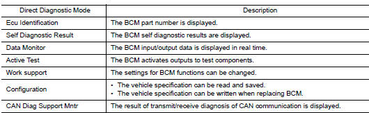
SYSTEM APPLICATION
BCM can perform the following functions.
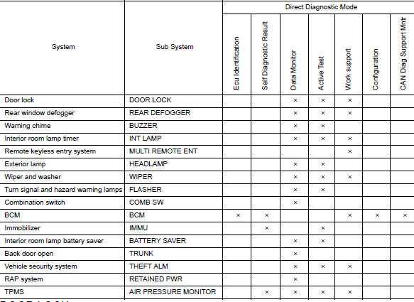
DOOR LOCK
DOOR LOCK : CONSULT Function (BCM - DOOR LOCK)
SELF DIAGNOSTIC RES
Refer to BCS-108, "DTC Index".
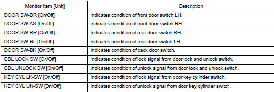
DATA MONITOR
ACTIVE TEST

WORK SUPPORT
* : Initial setting
MULTI REMOTE ENT
MULTI REMOTE ENT : CONSULT Function (BCM - MULTI REMOTE ENT)
WORK SUPPORT

 Preparation
Special Service Tool
The actual shapes of the tools may differ from those illustrated here.
Tool number
(TechMate No.)
Tool name
Tool number
(TechMate No.)
Tool name
...
 ECU diagnosis information
BCM, IPDM E/R
List of ECU Reference
...
Other materials:
Service data and specifications (SDS)
Wheel Alignment (Unladen*1)
*1: Fuel, engine coolant, and lubricants are full. Spare tire, jack, hand
tools, and mats are in designated positions.
Ball Joint
Wheelarch Height (Unladen*)
*: Fuel, engine coolant, and lubricants are full. Spare tire, jack, hand
tools, and mats are i ...
Cruise control operations
The cruise control allows driving at a speed between
25 - 89 MPH (40 - 144 km/h) without
keeping your foot on the accelerator pedal.
To turn on the cruise control, push the
ON┬ĘOFF switch ON. The CRUISE indicator light
in the vehicle information display will illuminate.
To set cruising spe ...
Symptom diagnosis
ENGINE DOES NOT START WHEN INTELLIGENT KEY IS INSIDE OF VEHICLE
Description
Engine does not start when push-button ignition switch is pressed while
carrying Intelligent Key.
NOTE:
Check that vehicle is under the condition shown in ŌĆ£Conditions
of vehicleŌĆØ before starting diagnos ...
