Nissan Rogue Service Manual: System
CHARGING SYSTEM
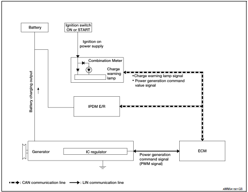
CHARGING SYSTEM : System Description
The generator provides DC voltage to operate the vehicle's electrical system and to keep the battery charged.
The voltage output is controlled by the IC regulator.
SYSTEM DIAGRAM
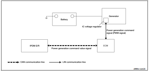
POWER GENERATION VOLTAGE VARIABLE CONTROL SYSTEM
POWER GENERATION VOLTAGE VARIABLE CONTROL SYSTEM : System Description
ECM transmits a target power generation voltage signal received from IPDM E/R to the generator via LIN communication.
The generator includes a self-diagnosis function and transmits a diagnosis signal to ECM via LIN communication when detecting a malfunction. When ECM receives a diagnosis signal, ECM detects DTC and transmits a charge warning lamp request signal to the combination meter to turn ON the charge warning lamp.
SYSTEM DIAGRAM
 Component parts
Component Parts Location
Combination meter
Engine room right side
Engine room left side
No.
Component part
Description
1
Combination meter (Charge ...
 Wiring diagram
CHARGING SYSTEM
Wiring Diagram
...
Other materials:
Rear disc brake
Brake Burnishing
CAUTION:
Burnish contact surfaces between brake pads and disc brake
rotor according to the following procedure
after refinishing the disc brake rotor, replacing brake pads or if a soft
pedal occurs at very low
mileage.
Be careful of vehicle speed. Brakes ...
B142A ignition voltage
Description
DTC B142A IGNITION VOLTAGE
Ignition voltage is supplied to the air bag diagnosis sensor unit when the
ignition is in the ON position. The air
bag diagnosis sensor unit will monitor for low or high ignition voltage.
PART LOCATION
Refer to SRC-6, "Component Parts Location" ...
Precaution
Precaution for Supplemental Restraint System (SRS) "AIR BAG" and "SEAT
BELT
PRE-TENSIONER"
The Supplemental Restraint System such as “AIR BAG” and “SEAT BELT PRE-TENSIONER”,
used along
with a front seat belt, helps to reduce the risk or severity of injury to the
...
