Nissan Rogue Service Manual: S connector circuit
Description
The starter motor magnetic switch is supplied with power when the ignition switch is turned to the START position while the selector lever is in the P (Park) or N (Neutral) position.
Diagnosis Procedure
Regarding Wiring Diagram information, refer to STR-7, "Wiring Diagram".
CAUTION: Perform diagnosis under the condition that engine cannot start by the following procedure.
- Remove fuel pump fuse.
- Crank or start the engine (where possible) until the fuel pressure is released.
1.CHECK “S” CONNECTOR CIRCUIT
- Turn ignition switch OFF.
- Disconnect starter motor connector.
- Shift selector lever to “P” (Park) or “N” (Neutral) position.
- Check voltage between starter motor harness connector and ground.
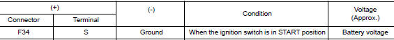
Is the inspection result normal? YES >> “S” circuit is OK. Further inspection is necessary. Refer to STR-11, "Work Flow (With GR8-1200 NI)" or STR-15, "Work Flow (Without GR8-1200 NI)".
NO >> GO TO 2.
2.CHECK HARNESS CONTINUITY (OPEN CIRCUIT)
- Disconnect IPDM E/R connector.
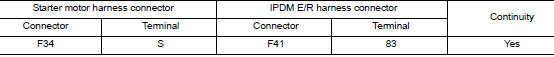
- Check continuity between starter motor harness connector and the IPDM E/R harness connector
- Check continuity between starter motor terminal S and ground.

Is the inspection result normal? YES >> Further inspection is necessary. Refer to STR-11, "Work Flow (With GR8-1200 NI)" or STR-15, "Work Flow (Without GR8-1200 NI)".
NO >> Repair or replace the harness or connectors.
Symptom diagnosis
STARTING SYSTEM
Symptom Table
| Symptom | Reference |
| No normal cranking | Refer to STR-11, "Work Flow (With GR8-1200 NI)" or STR-15, "Work Flow (Without GR8-1200 NI)". |
| Starter motor does not rotate |
 B terminal circuit
Description
Terminal “B” is constantly supplied with battery power.
Diagnosis Procedure
Regarding Wiring Diagram information, refer to STR-7, "Wiring Diagram".
CAUTION:
Perform diag ...
 Removal and installation
STARTER MOTOR
Exploded View
REMOVAL
Transaxle assembly
Starter motor
Lower bolt
Upper bolt
Removal and Installation
REMOVAL
Remove battery tray. Refer to PG-77, & ...
Other materials:
Settings
The setting mode allows you to change the information
displayed in the vehicle information display:
Driver Assistance
Clock
Meter Settings
Vehicle Settings
Maintenance
Alarm
Tire Pressure
Unit
Language
Factory Reset
...
Battery
Exploded View
Battery tray liner
Battery frame
Battery
Battery rod
Battery cover
Battery tray
Front
Removal and Installation (Battery)
REMOVAL
Pull back cover of battery positive terminal.
Loosen the battery terminal nuts and disconnect the battery ...
Moonroof switch
Removal and Installation
REMOVAL
Remove map lamp assembly. Refer to INL-55, "Removal and Installation".
Using a suitable tool release clip from harness connector.
: Clip
Using a suitable tool release pawls and remove moonroof switch
finisher (1).
Using a ...
