Nissan Rogue Service Manual: Rocker cover
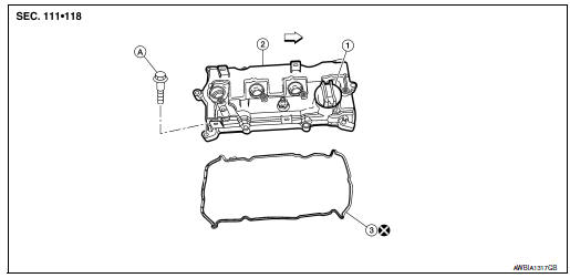
- Oil filler cap
- Rocker cover
- Rocker cover gasket
- Refer to INSTALLATION
 Engine front
Removal and Installation
REMOVAL
- Remove intake manifold. Refer to EM-26, "Removal and Installation".
- Remove wheel and tire (RH) using a power tool.
- Remove engine under cover. Refer toEXT-37, "ENGINE UNDER COVER : Removal and Installation".
- Remove fender protector side cover. Refer to EXT-28, "FENDER PROTECTOR : Exploded View".
- Remove drive belt. Refer to EM-13, "Removal and Installation".
- Remove the RH engine mount torque rod. Refer to EM-81, "Exploded View".
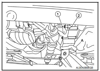
- Use a suitable jack (A) to securely support the bottom of the engine (1) and the transaxle assembly (2).
CAUTION: Put a piece of wood or an equivalent as the supporting surface and secure in a stable condition.
- Remove A/C line bracket bolt.
Engine front
- Remove harness grounds from engine mounting bracket (RH).
- Remove harness retainers from engine mounting bracket (RH).
- Remove the engine mounting bracket (RH). Refer to EM-81, "Exploded View"
- Remove the engine mounting bracket (LH). Refer to EM-81, "Exploded View"
- Disconnect the PCV hose.
- Disconnect harness connector from intake valve timing control solenoid valve. Refer to EM-44, "Exploded View"
- Disconnect harness connector from intermediate valve timing control solenoid valve. Refer to EM-44, "Exploded View"
- Disconnect harness connector from exhaust valve timing control solenoid valve. Refer to EM-44, "Exploded View"
- Disconnect harness connector from camshaft position sensors. Refer to EM-64, "Exploded View"
- Remove the spark plugs. Refer to EM-17, "Removal and Installation".
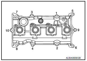
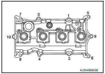
- Loosen the bolts in the numerical order as shown using power tool.
- Remove the rocker cover and the rocker cover gasket. Discard
the rocker cover gasket.
CAUTION: Do not reuse the rocker cover gasket.
- Remove the oil filler cap, (if necessary).
INSTALLATION
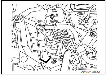
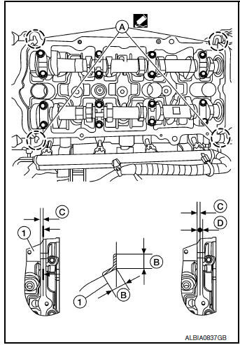
- Apply liquid gasket to the position shown (A) with the following procedure:
- Apply liquid gasket to joint part of No.1 camshaft bracket (1) and cylinder head.
- Apply liquid gasket in a 90° degree angle (B).
- Use Genuine Silicone RTV Sealant, or equivalent. Refer to GI-22, "Recommended Chemical Products and Sealants".
(B) : 10 mm (0.39 in)
(C) : 4 mm (0.16 in)
(D) : 5 mm (0.20 in)
- Install rocker cover gasket to rocker cover.
NOTE: The rocker cover gasket must be securely installed in the groove in the rocker cover.
- Install the rocker cover and rocker cover gasket onto the cylinder head.
- Tighten the rocker cover bolts to specification in two steps in the order shown.
Step 1 : 1.96 N·m (0.20 kg-m, 17 in-lb)
Step 2 : 8.33 N·m (0.85 kg-m, 74 in-lb)
- Installation of the remaining components is in the reverse order of removal.
- Inspect for engine oil leaks. Refer to LU-7, "Inspection".
 Ignition coil
Exploded View
Ignition coil
Spark plug
Rocker cover
Removal and Installation
REMOVAL
Remove air duct assembly. Refer to EM-24, "Exploded View" .
Dis ...
 Fuel injector and fuel tube
Exploded View
Rocker cover
Cylinder head
Fuel tube
Clip
O-ring (green)
Fuel injector
O-ring (black)
Front
Removal and Installation
WARNING:
& ...
Other materials:
System
WARNING CHIME SYSTEM
WARNING CHIME SYSTEM : System Description
SYSTEM DIAGRAM (WITH INTELLIGENT KEY SYSTEM)
SYSTEM DIAGRAM (WITHOUT INTELLIGENT KEY SYSTEM)
COMBINATION METER INPUT/OUTPUT SIGNAL (CAN COMMUNICATION SIGNAL)
Input signal
Output signal
BCM INPUT/OUTPUT SIGNAL (CAN ...
Air conditioner system refrigerant and oil recommendations
The air conditioner system in your NISSAN
vehicle must be charged with the refrigerant
HFC-134a (R-134a) and NISSAN A/C
system oil Type ND-OIL8 or the exact
equivalents.
CAUTIONThe use of any other refrigerant or oil will
cause severe damage to the air conditioning
system and will ...
Periodic maintenance
FRONT WHEEL HUB AND KNUCKLE
Inspection
Move the wheel hub and bearing in an axial direction by hand to verify
that looseness of wheel hub and
bearing exists. If any looseness exists, replace the wheel hub and bearing.
Axial end play : Refer to FAX-32, "Wheel Bearing".
Rota ...
