Nissan Rogue Service Manual: Removal and installation
REAR WHEEL HUB AND HOUSING
Exploded View
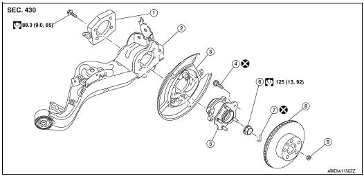
- Axle housing
- Suspension arm
- Back plate
- Hub bolt
- Wheel hub and bearing
- Wheel hub lock nut
- Cotter pin
- Disc brake rotor
- Plug
Removal and Installation
REMOVAL
- Remove the wheel and tire using power tool. Refer to WT-57, "Adjustment".
- Remove the bolt and separate the rear wheel sensor from the axle housing. Position the rear wheel sensor and the harness aside. Refer to BRC-134, "REAR WHEEL SENSOR : Removal and Installation".
CAUTION:
- Pull out the rear wheel sensor, being careful to turn it as little as possible. Do not pull on the wheel sensor harness.
- Failure to remove the rear speed sensor from the axle housing may result in damage to the rear wheel sensor.
- Remove torque member bolts using power tool, leaving the brake hose
attached. Position brake caliper
aside with wire. Refer to BR-42, "BRAKE CALIPER ASSEMBLY : Exploded View".
CAUTION: Do not depress brake pedal while brake caliper is removed.
- Put alignment marks on the disc brake rotor and on the wheel hub and
bearing. Remove the disc brake
rotor.
CAUTION: Do not drop disc brake rotor.
- Remove the cotter pin.
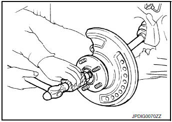
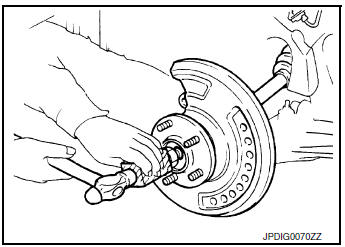
- Loosen, but do not remove, the wheel hub lock nut from the drive shaft using power tool.
- Tap the wheel hub lock nut with a piece of wood to disengage the drive shaft from the wheel hub and bearing.
CAUTION:
- Do not place drive shaft joint at an extreme angle. Be careful not to overextend slide joint.
- Do not allow drive shaft to hang without support.
NOTE: Use a suitable puller if drive shaft cannot be separated from the wheel hub and bearing.
- Remove the wheel hub lock nut.
- Remove the hub bolts and the wheel hub and bearing.
- Position the parking brake and back plate aside with wire.
- Remove the coil spring and spring seats. Refer to RSU-10, "Removal and Installation - AWD".
- Remove the axle housing.
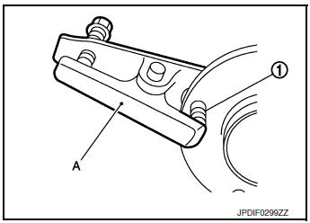
- If necessary, remove the wheel studs (1) from the wheel hub and bearing using a suitable tool (A).
CAUTION:
- Remove the wheel studs only when necessary.
- Do not hammer the wheel studs or damage to the wheel hub and bearing may occur.
- Pull out the wheel studs in a direction perpendicular to the wheel hub and bearing.
- Inspect the components. Refer to RAX-14, "Inspection".
INSTALLATION
Installation is in the reverse order of removal.
- Place a washer (A) as shown to install the wheel studs (1) by using the tightening force of the nut (B).
CAUTION:
- Check that there is no clearance between wheel stud and the wheel hub and bearing.
- Do not reuse wheel stud.
- Clean the mating surfaces of the wheel hub lock nut and the wheel hub
and bearing.
CAUTION: Do not apply lubricating oil to these mating surface.
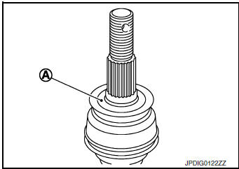
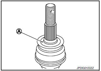
- Clean the mating surfaces of the joint sub-assembly and the wheel
hub and bearing. Apply Molykote M77 lubricant to the surface (A)
of the joint sub-assembly.
CAUTION: Apply lubricant to cover the entire flat surface of joint subassembly.
NOTE: Always check with the Parts Department for the latest parts information.
Amount of lubricant : RAX-27, "Drive Shaft"
- Hold the wheel hub and bearing. Tighten the wheel hub lock nut.
CAUTION:
- Since the drive shaft is assembled by press-fitting, use a torque wrench to tighten the wheel hub lock nut. Do not use a power tool.
- Too much torque causes axle noise. Too little torque causes wheel bearing looseness. Tighten the wheel hub lock nut to the specification.
- When installing a cotter pin, securely bend the cotter pin to prevent rattles.
CAUTION: Do not reuse cotter pin.
- Install the rear wheel sensor to the axle housing. Refer to BRC-134, "REAR WHEEL SENSOR : Removal and Installation".
CAUTION:
- Before installing, make sure there is no foreign material such as iron fragments adhered to the pickup part of the rear wheel sensor.
- When installing, make sure there is no foreign material such as
iron fragments adhered to the pickup
part of the rear wheel sensor. Make sure no foreign material has been caught
in the sensor rotor.
Remove any foreign material and clean the mount.
- Check that the wheel hub and bearing operates smoothly.
- Align the matching marks on the disc brake rotor and on the wheel hub and bearing.
- Perform the inspection after installation. Refer to RAX-14, "Inspection".
- Perform the final tightening of each part under unladen conditions, which were removed when removing wheel hub and bearing.
Inspection
INSPECTION AFTER REMOVAL
Wheel Hub and Bearing
Check the wheel hub and bearing for wear, cracks, and damage. Replace if necessary.
Axle Housing
Check the axle housing for wear, cracks and damage. Replace if necessary.
Ball Joint Inspection Check for boot breakage, axial looseness, and torque of suspension arm ball joint. Refer to RSU-5, "Inspection and Adjustment".
INSPECTION AFTER INSTALLATION
- Adjust parking brake operation (stroke). Refer to PB-4, "Inspection and Adjustment".
- Check the wheel alignment. Refer to FSU-7, "Inspection".
- Adjust neutral position of steering angle sensor. Refer to BRC-70, "Work Procedure".
REAR DRIVE SHAFT
Exploded View
REMOVAL
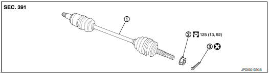
- Drive shaft
- Wheel nub lock nut
- Cotter pin
Removal and Installation
REMOVAL
- Remove the wheel and tire using power tool. Refer to WT-60, "Exploded View".
- Remove the bolt and separate the rear wheel sensor from the axle housing. Position the rear wheel sensor and the harness aside. Refer to BR-42, "BRAKE CALIPER ASSEMBLY : Exploded View".
CAUTION:
- Failure to remove the rear speed sensor from the axle housing may result in damage to the rear wheel sensor.
- Pull out the rear wheel sensor, being careful to turn it as little as possible. do not pull on wheel sensor harness.
- Remove torque member bolts using power tool, leaving the brake hose
attached. Position brake caliper
aside with wire. Refer to BR-43, "BRAKE CALIPER ASSEMBLY : Removal and
Installation".
CAUTION: Do not depress brake pedal while brake caliper is removed.
- Put alignment marks on the disc brake rotor and the wheel hub and
bearing. Remove the disc brake rotor.
CAUTION: Do not drop the disc brake rotor.
- Remove the cotter pin.
- Loosen but do not remove, the wheel hub lock nut from the drive shaft using power tool.
- Tap the wheel hub lock nut with a piece of wood to disengage the drive shaft from the wheel hub and bearing.
CAUTION:
- Do not place drive shaft joint at an extreme angle. Be careful not to overextend slide joint.
- Do not allow the drive shaft to hang without support.
NOTE: Use a suitable puller if the drive shaft cannot be separated from the wheel hub and bearing.
- Remove the wheel hub lock nut.
- Remove the coil spring and spring seats. Refer to BRC-133, "REAR WHEEL SENSOR : Exploded View".
- Remove the bolts and the suspension member stay. Refer to RSU-21, "Exploded View".
- Remove drive shaft from final drive.
INSTALLATION
Installation is in the reverse order of removal.
- Clean the mating surfaces of the joint sub-assembly and the wheel
hub and bearing. Apply Molykote M77 lubricant to surface (A) of
joint sub-assembly.
CAUTION: Apply lubricant to cover entire flat mating surface of joint subassembly.
NOTE: Always check with the Parts Department for the latest parts information.
Amount of lubricant : RAX-27, "Drive Shaft"
Hold the wheel hub and bearing. Tighten the wheel hub lock nut.
CAUTION:
- Since the drive shaft is assembled by press-fitting, use a torque wrench to tighten the wheel hub lock nut. Do not use a power tool.
- Too much torque causes axle noise. Too little torque causes wheel bearing looseness. Tighten the wheel hub lock nut to the specification.
- When installing the cotter pin, securely bend the cotter pin to prevent rattles.
CAUTION: Do not reuse cotter pin.
- Install the rear wheel sensor to the axle housing Refer to BRC-133, "REAR WHEEL SENSOR : Exploded View".
CAUTION:
- Before installing, make sure there is no foreign material such as iron fragments adhered to the pick-up part of the rear wheel sensor.
- When installing, make sure there is no foreign material such as iron fragments on and in the hole in the axle housing for the rear wheel sensor. Make sure no foreign material has been caught in the sensor rotor. Remove any foreign material and clean the mount.
- Perform the final tightening of each of parts under unladen conditions, which were removed when removing wheel hub and bearing.
- Check that the hub and bearing operates smoothly.
- Align the matching marks on the disc brake rotor and on the wheel hub and bearing.
- Perform the inspection after installation. Refer to RAX-14, "Inspection".
Inspection
INSPECTION AFTER REMOVAL
- Move joint up/down, left/right, and in the axial direction. Check for motion that is not smooth and for significant looseness.
- Check boot for cracks or other damage, and also for grease leakage.
- If a malfunction is found, disassemble drive shaft, and then replace components as necessary.
 Periodic maintenance
REAR WHEEL HUB AND HOUSING
Inspection
INSPECTION
Make sure the conditions (looseness, back lash) of each component and
component conditions (wear, damage)
are normal.
WHEEL HUB AND BEARING INSP ...
 Unit disassembly and assembly
REAR DRIVE SHAFT
Exploded View
DISASSEMBLY
Circular clip
Dust shield
Slide joint housing
Snap ring
Spider assembly
Boot band
Boot
Shaft
Circular clip
Joint ...
Other materials:
Changing engine oil filter
>
Changing engine oil filter
Park the vehicle on a level surface and apply
the parking brake.
Turn the engine off.
Place a large drain pan under the oil filter B .
Remove pins C from the right engine protector
located inside right wheel well, remove
protector. Remove oil ...
Precaution
Precaution for supplemental restraint system (srs) "air bag" and "seat
belt
pre-tensioner"
The Supplemental Restraint System such as “AIR BAG” and “SEAT BELT PRE-TENSIONER”,
used along
with a front seat belt, helps to reduce the risk or severity of injury to the
...
How to read the displayed lines
Guiding lines which indicate the vehicle width
and distances to objects with reference to the
vehicle body line A are displayed on the monitor.
Distance guide lines:
Indicate distances from the vehicle body.
Red line 1 : approx. 0.5 m (1.5 ft)
Yellow line 2 : approx. 1 m (3 ...
