Nissan Rogue Service Manual: Removal and installation
EXHAUST SYSTEM
Exploded View
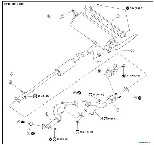
- Exhaust diffuser
- Muffler assembly
- Mounting rubber
- Mounting rubber
- Mounting rubber
- Ring gasket
- Front exhaust tube
- Mounting rubber
- Exhaust gasket
- Oxygen sensor 2
- Center exhaust tube
- Catalyst shroud
- To exhaust manifold and three way catalyst
Removal and Installation
WARNING:
- Perform the procedures with the exhaust system fully cooled down to avoid injury from the hot exhaust system.
- Be careful not to cut your hand on the catalyst shroud edge.
CAUTION: Use genuine NISSAN exhaust system parts or equivalent, which are specifically designed for heat resistance, corrosion resistance, and shape.
REMOVAL
- Remove exhaust system components using power tool.
- Remove heated oxygen sensor 2 using suitable tool.
INSTALLATION
Installation is in the reverse order of removal.
CAUTION:
- Do not reuse exhaust gasket.
- Do not reuse nuts securing front exhaust tube to exhaust manifold and three way catalyst.
- Do not allow foreign substances to contact new exhaust gasket.
- Be sure to install ring gasket to prevent catching when tightening.
- Do not reuse ring gasket.
- Ensure flexible portion of front exhaust tube is free from deformation.
- During installation, take care not to deform mounting rubbers. After installing, the mounting rubbers shall show no excessive movement, twisting, or elongation. To facilitate installation, a neutral detergent may be used.
- Mounting rubbers installed at either side of muffler are to be installed in accordance with paint marks. Mounting rubber at LH side is installed with white paint mark facing forward. Mounting rubber at RH side is installed with white paint mark facing rearward.
- Do not spray exhaust tubes, muffler, heated oxygen sensor 2, or catalyst shroud with anti-corrosive wax.
- If catalyst shroud is badly deformed, repair or replace it. If deposits, such as mud, pile up on the catalyst shroud, remove them.
- When installing catalyst shroud, avoid large gaps or interference between catalyst shroud and exhaust pipe.
- Temporarily tighten fasteners and check each part for interference with other components, and then tighten fasteners to specification.
- Discard any heated oxygen sensor 2 which has been dropped.
- Before installing a new heated oxygen sensor 2, clean exhaust system threads using Tool.
Oxygen sensor thread cleaner : J-43897-18
- Tighten heated oxygen sensor 2 using suitable tool. Do not use impact wrench.
- Do not over tighten heated oxygen sensor 2. Doing so may cause damage to the heated oxygen sensor 2, resulting in the ŌĆ£MILŌĆØ coming on.
- Remove deposits from the sealing surface of each connection. Connect them securely to avoid exhaust gas leaks.
Inspection
INSPECTION AFTER INSTALLATION
- Check clearance between tail tube and rear bumper is even.
- With engine running, check exhaust tube joints for gas leakage and unusual noises.
- Check to ensure that mounting brackets and mounting rubbers are installed properly and free from undue stress. Improper installation could result in excessive noise and vibration.
 Periodic maintenance
EXHAUST SYSTEM
Inspection
Check exhaust pipes, muffler, and mounting for improper attachment,
leakage, cracks, damage or deterioration.
If anything is found, repair or replace damaged par ...
 Starting System
...
Other materials:
Anti-pinch system does not operate normally (driver side)
Diagnosis Procedure
1.PERFORM INITIALIZATION PROCEDURE
Initialization procedure is executed and operation is confirmed.
Refer to PWC-27, "ADDITIONAL SERVICE WHEN REMOVING BATTERY NEGATIVE TERMINAL :
Special
Repair Requirement".
Is the inspection result normal?
YES >> Insp ...
Fuses
Two types of fuses are used. Type A is used in
the fuse boxes in the engine compartment. Type
B is used in the passenger compartment fuse
box.
Type A fuses are provided as spare fuses. They
are stored in the passenger compartment fuse
box.
Type A fuses can be installed in the engine
co ...
Heater and Air Conditioner (automatic)
(if so equipped)
Heater and Air Conditioner
(front defroster) button
Temperature control dial (driverŌĆÖs side) /
ON-OFF button
MODE (manual air flow control) button
Display screen
A/C (air conditioner) button
Temperature control dial (passengerŌĆÖs
side)/DUAL (pa ...
