Nissan Rogue Service Manual: Removal and installation
AUDIO UNIT
Exploded View
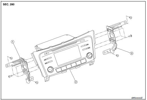
- Audio unit bracket (LH)
- Audio unit
- Audio unit bracket (RH)
Removal and Installation
REMOVAL
- Disconnect the negative battery terminal. Refer to PG-75, "Removal and Installation (Battery)".
- Remove A/C switch (AUTOMATIC AIR CONDITIONING) or front air
control (MANUAL AIR CONDITIONING).
Refer to HAC-102, "Removal and Installation" (AUTOMATIC AIR CONDITIONING) or HAC-181, "Removal and Installation" (MANUAL AIR CONDITIONING).
- Remove instrument finisher B. Refer to IP-16, "INSTRUMENT FINISHER B : Removal and Installation".
- Remove instrument finisher E. Refer to IP-16, "INSTRUMENT FINISHER E : Removal and Installation".
- Remove the audio unit screws, then pull out the audio unit.
- Disconnect the harness connectors from the audio unit and remove.
- Remove the audio unit bracket (LH/RH) screws and the audio unit brackets (LH/RH) (if necessary).
INSTALLATION
Installation is in the reverse order of removal.
STEERING SWITCHES
Exploded View
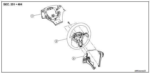
- Steering wheel rear finisher
- Steering wheel
- Steering switches
 Pawl
Pawl
Removal and Installation
REMOVAL
NOTE: The steering switches are serviced as an assembly.
- Remove steering wheel. Refer to ST-11, "Removal and Installation".
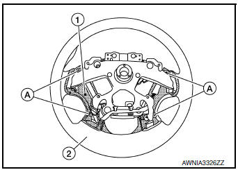
- Release pawls on the steering wheel rear finisher and remove.
- Remove screws (A) and steering switches (1) from steering wheel (2).
INSTALLATION
Installation is in the reverse order of removal.
FRONT TWEETER
Removal and Installation
REMOVAL
- Remove defroster grille. Refer to VTL-12, "DEFROSTER GRILLE : Removal and Installation".
- Remove bolts and pull out the front tweeter.
- Disconnect the harness connector from the front tweeter and remove.
INSTALLATION
Installation is in the reverse order of removal.
FRONT DOOR SPEAKER
Exploded View
- Front door speaker
Removal and Installation
REMOVAL
- Remove front door finisher. Refer to INT-15, "Removal and Installation".
- Remove front door speaker bolts, then pull out front door speaker.
- Disconnect the harness connector from front door speaker and remove.
INSTALLATION
Installation is in the reverse order of removal.
REAR DOOR SPEAKER
Exploded View
- Rear door speaker
Removal and Installation
REMOVAL
- Remove rear door finisher. Refer to INT-18, "Removal and Installation".
- Remove rear door speaker bolts, then pull out rear door speaker.
- Disconnect the harness connector from the rear door speaker and remove.
INSTALLATION
Installation is in the reverse order of removal.
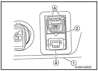
USB INTERFACE AND AUX IN JACK
Removal and Installation
REMOVAL
- Remove cluster lid C. Refer to IP-21, "Removal and Installation".
- Release the pawls (A) on the back of USB interface and AUX in jack (2), then remove from the front of cluster lid C (1).
INSTALLATION
Installation is in the reverse order of removal.
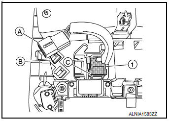
MICROPHONE
Removal and Installation
REMOVAL
- Remove the map lamp assembly. Refer to INL-55, "Removal and Installation".
- Release harness connector (A) by sliding rearward to remove from the pawl (B).
- Release pawls (C) and remove the microphone (1) from the front room/map lamp assembly.
INSTALLATION
Installation is in the reverse order of removal.
REAR VIEW CAMERA
Removal and Installation
REMOVAL
- Remove the back door outer finisher. Refer to EXT-50, "Removal and Installation".
- Release pawl, disconnect harness connector from rear view camera and remove.
INSTALLATION
Installation is in the reverse order of removal.
AUDIO ANTENNA
Removal and Installation
REMOVAL
- Remove the luggage side upper finisher (RH). Refer to INT-36, "LUGGAGE SIDE UPPER FINISHER : Removal and Installation".
- Partially lower headlining (rear). Refer to INT-30, "Removal and Installation".
- Disconnect harness connectors from antenna feeder.
- Remove nut from audio antenna and remove.
INSTALLATION
Installation is in the reverse order of removal.
Audio antenna nut : 6.5 N·m (0.66 kg-m, 58 in-lb)
CAUTION: If the audio antenna nut is not properly tightened, lower sensitivity of the antenna may be experienced.
If the nut is over tightened, this will deform the roof panel.
ANTENNA FEEDER
Feeder Layout
ANTENNA FEEDER LAYOUT
- Antenna base (antenna amp. and satellite antenna)
- Rod Antenna
- M503
- M502
- M130, M501
- M129, M500
- M126
- M124
 Symptom diagnosis
AUDIO SYSTEM
Symptom Table
RELATED TO AUDIO
Symptoms
Check items
Probable malfunction location
The disk cannot be removed
Audio unit
Malfunction in audio uni ...

Other materials:
Vents
Side
Adjust air flow direction by moving the vent
slides.
Open or close the vents by using the dial. Move
the dial toward the to open the
vents or
toward the to close them.
Center
Rear ...
Diagnosis system (IPDM E/R)
CONSULT Function (IPDM E/R)
APPLICATION ITEM
CONSULT performs the following functions via CAN communication with IPDM E/R.
Direct Diagnostic Mode
Description
Ecu Identification
The IPDM E/R part number is displayed.
Self Diagnostic Result
The IPDM E/R sel ...
Anti-lock Braking System (ABS)
WARNING
The Anti-lock Braking System (ABS) is a
sophisticated device, but it cannot prevent
accidents resulting from careless
or dangerous driving techniques. It can
help maintain vehicle control during
braking on slippery surfaces. Remember
that stopping dis ...
