Nissan Rogue Service Manual: Rear disc brake
Exploded View
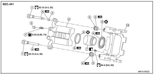
- Sliding pin bolt
- Sliding pin bolt bushing
- Cap
- Bleeder valve
- Brake caliper body
- Piston seal
- Piston
- Piston boot
- Sliding pin boot
- Torque member
- Rubber grease
 Apply brake fluid
Disassembly and Assembly
DISASSEMBLY
- Remove the brake caliper from the vehicle. Refer to BR-43, "BRAKE CALIPER ASSEMBLY : Removal and Installation".
- Remove sliding pin boots from torque member.
- Remove sliding pin bolt bushing from sliding pin bolt.
- Place a wooden block in the cylinder body and blow air from
union bolt hole to remove piston and piston boot.
WARNING: Do not get fingers caught between pistons and brake caliper body.
CAUTION: Do not reuse piston boot.
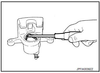
- Remove piston seal from brake caliper body using suitable tool.
CAUTION:
- Do not damage cylinder inner wall.
- Do not reuse piston seal.
- Remove bleeder valve and cap.
INSPECTION AFTER DISASSEMBLY
Brake Caliper Body
Check the inner wall of the brake caliper body for rust, wear, cracks or damage. Replace the brake caliper body if any abnormal condition is detected.
CAUTION: Always clean with new brake fluid. Do not clean with mineral oil such as gasoline and light oil.
Torque Member
Check the torque member for rust, wear, cracks or damage. Replace the torque member if any abnormal condition is detected.
Piston
Check the surface of the piston for rust, wear, cracks or damage. Replace the piston if any abnormal condition is detected.
CAUTION: Piston sliding surface is plated. Do not polish with sandpaper.
Sliding Pin and Sliding Pin Bolt Boot
Check the sliding pins and sliding pin bolt boots for rust, wear, cracks or damage. Replace the parts if any abnormal condition is detected.
ASSEMBLY
- Install bleeder valve and cap.
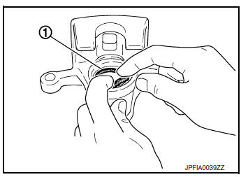
- Apply rubber grease to piston seal (1), and install it to the brake caliper body.
CAUTION: Do not reuse piston seal.
- Apply rubber grease to piston boot (1). Cover the piston (2) end with the piston boot, and then install cylinder side lip on the piston boot securely into the groove on brake caliper body.
CAUTION: Do not reuse piston boot.
- Apply brake fluid to piston (1). Push piston into brake caliper
body by hand and push piston boot (2) piston side lip into the
piston groove.
CAUTION: Press the piston evenly and vary the pressing point to prevent cylinder inner wall from contact.
- Apply rubber grease to bushing; install bushing to sliding pin bolt.
- Install sliding pin boots to torque member.
- Install the brake caliper to the vehicle. Refer to BR-43, "BRAKE CALIPER ASSEMBLY : Removal and Installation".
INSPECTION AFTER INSTALLATION
- Check the drag of rear disc brake. If any drag is found, follow the procedure described below.
- Remove brake pads.
- Using a suitable tool, press the pistons into the brake caliper
body.
CAUTION: Do not damage the piston boots.
- Install brake pads.
- Depress the brake pedal several times.
- Check the drag of rear disc brake again. If any drag is found, disassemble the brake caliper body.
- Burnish contact surfaces after refinishing or replacing disc rotors or
if a soft pedal occurs at very low mileage.
Refer to BR-19, "Brake Burnishing".
 Front disc brake
BRAKE CALIPER ASSEMBLY (1 PISTON TYPE)
BRAKE CALIPER ASSEMBLY (1 PISTON TYPE) : Exploded View
Torque member
Bushing
Piston boot
Slide pin boot
Slide pin
Piston
&nb ...
 Service data and specifications (SDS)
General specifications
Brake pedal
Brake booster
Front Disc Brake
Rear disc brake
...
Other materials:
Precaution
Precaution for Supplemental Restraint System (SRS) "AIR BAG" and "SEAT
BELT
PRE-TENSIONER"
The Supplemental Restraint System such as “AIR BAG” and “SEAT BELT PRE-TENSIONER”,
used along
with a front seat belt, helps to reduce the risk or severity of injury to the
...
Power window motor
DRIVER SIDE
DRIVER SIDE : Description
Door glass moves UP/DOWN by receiving the signal from main power window and
door lock/unlock switch.
DRIVER SIDE : Component Function Check
1. CHECK FRONT POWER WINDOW MOTOR LH OPERATION
Check front power window motor LH operation with main power window a ...
Preparation
Special Service Tool
The actual shape of the tools may differ from those tools illustrated here.
Tool number
(TechMate No.)
Tool name
Description
—
(J-50190)
Signal Tech II
Activate and display TPMS transmitter IDs
Display tire ...
