Nissan Rogue Service Manual: Preparation
Special service tools
The actual shape of the tools may differ from those illustrated here.
|
Tool number (TechMate No.) Tool name |
Description | |
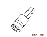
| — (J-48891) Spark plug socket |  |
Removing and installing spark plug |
| KV10111100 (J-37228) Seal cutter | 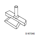 |
Removing oil pan and timing chain case |
| KV10112100 (BT-8653-A) Torque angle meter | 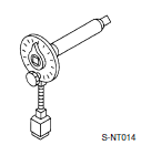 |
Tightening bolts for bearing cap, cylinder head, etc. |
Commercial service tools
|
Tool number (TechMate No.) Tool name |
Description |
|
| Pulley puller |
|
Removing crankshaft pulley |
| Piston ring compresso |
|
Installing piston assembly into cylinder bore |
| Pulley holder |
|
Crankshaft pulley removing and installing |
| Valve seat cutter set |
|
Finishing valve seat dimensions |
| Socket |
|
Removing and installing flywheel Size: T55 |
| Piston ring expander |
|
Removing and installing piston ring |
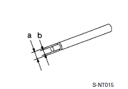
| Valve guide drift |
|
Removing and installing valve guide
Intake & Exhaust: a: 9.5 mm (0.374 in) dia. b: 5.5 mm (0.217 in) dia. |
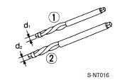
| Valve guide reamer |
|
Intake & Exhaust: |
| Anti-seize lubricant i.e.: (PermatexTM 133AR or equivalent meeting MIL specification MIL-A-907) |
|
Lubricating oxygen sensor thread cleaning tool when reconditioning exhaust system threads |
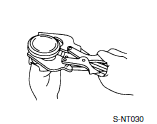
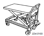
| Manual lift table caddy |
|
Removing and installing engine |
| KV10107902 (J-38959) Valve oil seal puller with adapter (1) |
|
Removing valve oil seal |
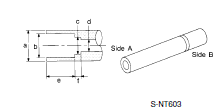
| KV10115600 (J-38958) Valve oil seal drift |
|
Installing valve oil seal Use side A. Unit: mm (in) |
| Tube presser |
|
Pressing the tube of liquid gasket |
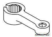
| Exhaust gas sensor wrench |
|
Removing exhaust gas sensor |
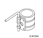
| KV10116200 (J-26336-A) Valve spring compressor 1. KV10115900 (J-26336-20) Attachment 2. KV10109220 ( — ) Adapter |
|
Disassembling valve mechanism Part (1) is a component of KV10116200 (J- 26336-A), but part (2) is not. |


 Symptom diagnosi
NOISE, VIBRATION, AND HARSHNESS (NVH) TROUBLESHOOTING
NVH troubleshooting - engine noise
Valve mechanism
Intake and exhaust valve
Water pump
Timing chain
Dr ...

Other materials:
Door outside lower molding
Exploded View
Rear door outside lower molding
Front door outside lower molding
Clip
Front
Removal and Installation
FRONT DOOR OUTSIDE LOWER MOLDING
Removal
Using a suitable tool (A) release clips from front door outside
lower molding (1) starting at the rear and work ...
Unit disassembly and assembly
ELECTRIC CONTROLLED COUPLING
Exploded View
Stud bolt
Connector bracket
Reamer bolt
Electric controlled coupling assembly
Wave spring
Drive pinion oil seal
Drive pinion lock nut
Pinion front bearing
Gear carrier
Collapsible spacer
Drive pinion adjusting shim
Pini ...
Service data and specifications (SDS)
Wheel Bearing
Drive Shaft
Drive Shaft Specifications
*Always check with the Parts Department for the latest parts information.
Dynamic Damper Specifications
Boot Band Specification
...
