Nissan Rogue Service Manual: Power switch illumination circuit
Description
Provides the power supply and the ground to control the power switch illumination.
Component Function Check
1.CHECK POWER SWITCH ILLUMINATION OPERATION
 CONSULT ACTIVE TEST
- Turn the power switch ON.
- Select “ENGINE SW ILLUMI” of “BCM” active test item.
- With operating the test items, check that the power switch illumination turns ON/OFF.
On : Power switch illumination ON
Off : Power switch illumination OFF
Does the power switch illumination turn ON/OFF? YES >> Power switch illumination circuit is normal.
NO >> Refer to INL-52, "Diagnosis Procedure".
Diagnosis Procedure
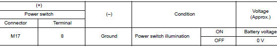
1.CHECK POWER SWITCH ILLUMINATION POWER SUPPLY OUTPUT
- Turn power switch OFF.
- Disconnect power switch connector.
- Check voltage between power switch harness connector and ground.
Is the inspection result normal? YES >> GO TO 4.
NO >> GO TO 2.
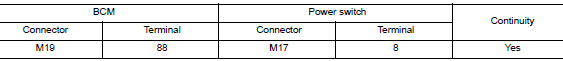
2.CHECK POWER SWITCH ILLUMINATION POWER SUPPLY OPEN CIRCUIT
- Turn the power switch OFF.
- Disconnect BCM connector.
- Check continuity between BCM harness connector and the power switch harness connector.
Is the inspection result normal? YES >> GO TO 3.
NO >> Repair or replace harnesses.
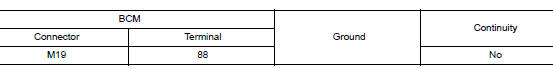
3.CHECK POWER SWITCH ILLUMINATION POWER SUPPLY SHORT CIRCUIT
Check continuity between BCM harness connector and ground.
Is the inspection result normal? YES >> Replace BCM. Refer to BCS-75, "Removal and Installation" (with intelligent Key system) or BCS- 135, "Removal and Installation" (without Intelligent Key system).
NO >> Repair or replace harnesses.
4.CHECK POWER SWITCH ILLUMINATION GROUND CIRCUIT
- Turn the power switch OFF.
- Check continuity between power switch harness connector and ground.

Is the inspection result normal? YES >> Replace power switch. Refer to SEC-112, "Removal and Installation".
NO >> Repair or replace harnesses.
 Luggage room lamp circuit
Description
Controls the luggage room lamp (ground side) to turn the luggage room lamp ON
and OFF.
Diagnosis Procedure
CAUTION:
Before performing the diagnosis, check that the following is norma ...
 Symptom diagnosis
INTERIOR LIGHTING SYSTEM SYMPTOMS
Symptom Table
CAUTION:
Perform the self-diagnosis with CONSULT before the symptom diagnosis. Perform
the trouble diagnosis
if any DTC is detected.
S ...
Other materials:
Door outside lower molding
Exploded View
Rear door outside lower molding
Front door outside lower molding
Clip
Front
Removal and Installation
FRONT DOOR OUTSIDE LOWER MOLDING
Removal
Using a suitable tool (A) release clips from front door outside
lower molding (1) starting at the rear and work ...
Preparation
Special Service Tool
The actual shape of the tools may differ from those illustrated here
Tool number
(TechMate No.)
Tool name
Description
KV101207S0
( — )
Unified fuel lock ring wrench
Removing and installing fuel tank lock ring
—
(J-45747)
...
Cylinder block
Exploded View
Cylinder block
Top ring
Second ring
Oil ring
Snap ring
Piston
Connecting rod
Piston pin
Connecting rod bearing
Rear oil seal
Reinforcement plate
Drive plate
Signal plate
Pilot convert ...
