Nissan Rogue Service Manual: Power supply and ground circuit
Diagnosis Procedure
Regarding Wiring Diagram information, refer to PCS-24, "Wiring Diagram".
1. CHECK FUSE AND FUSIBLE LINKS
Check that the following IPDM E/R fuse or fusible links are not blown.
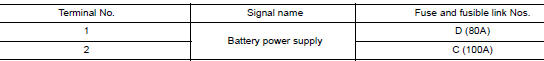
Is the fuse blown? YES >> Replace the blown fuse or fusible link after repairing the affected circuit.
NO >> GO TO 2.
2. CHECK BATTERY POWER SUPPLY CIRCUIT
- Disconnect IPDM E/R connector E118.
- Check voltage between IPDM E/R connector E118 and ground.
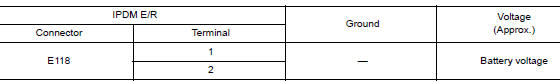
Is the inspection result normal? YES >> GO TO 3.
NO >> Repair or replace harness or connectors.
3. CHECK GROUND CIRCUIT
- Disconnect IPDM E/R connectors E119, E120 and E121.
- Check continuity between IPDM E/R connectors and ground.
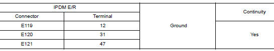
Is the inspection result normal? YES >> Inspection End.
NO >> Repair or replace harness or connectors.
 U1000 CAN COMM CIRCUIT
Description
CAN communication allows a high rate of information transmission through the
two communication lines
(CAN-H line and CAN-L line) connecting various control units in the system. Each
...
 Parking brake switch
Component Function Check
1.CHECK PARKING BRAKE SWITCH OPERATION
Check that brake warning lamp in combination meter turns ON/OFF when parking
brake is operated.
Is the inspection result normal?
...
Other materials:
Front wiper motor
Removal and Installation
REMOVAL
Remove the front drive assembly. Refer to WW-66, "Removal and
Installation".
Remove the bolts (A) from the front wiper drive assembly (1)
and the front wiper motor (2).
Separate the wiper motor (1) from the front wiper drive ...
Front seat
DRIVER SIDE
DRIVER SIDE : Exploded View
POWER SEAT
Headrest
Seatback support
Seatback board
Seatback heater (if equipped)
Seatback trim
Seatback pad
Seat cushion outer finisher (RH)
Seat cushion rear finisher
(RH)
Seat cushion inner fini ...
C1735 ignition signal
DTC Logic
NOTE:
The Signal Tech II Tool [- (J-50190)] can be used to perform the following
functions. Refer to the Signal Tech II
User Guide for additional information.
Activate and display TPMS sensor IDs
Display tire pressure reported by the TPMS sensor
Read TPMS DTC ...
