Nissan Rogue Service Manual: Parking brake system
Inspection and Adjustment
INSPECTION
Pedal Stroke
- Operate the parking brake pedal with a force of 196 N (20.0 kg-f, 44.1 lb-f). Check that the pedal stroke is within the specified number of notches. (Check it by listening to the clicks of the ratchet.)
Number of notches : Refer to PB-14, "Parking Brake Control".
- When brake warning lamp turns ON, check that the pedal stroke is within
the specified number of notches.
(Check it by listening to the clicks of the ratchet.)
Number of notches : Refer to PB-14, "Parking Brake Control".
Inspect Components
- Check each component for installation condition such as looseness.
- Check the parking brake components for bends, wear, cracks and or damage. Replace if damage is noted.
- Check the parking brake switch, and replace it if necessary. Refer to PB-7, "Exploded View".
ADJUSTMENT
- Secure the disc brake rotor using wheel nuts.
- Remove the instrument lower panel (LH). Refer to IP-22, "Removal and Installation".
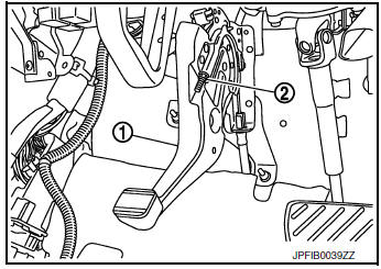
- Release the parking brake pedal (1) by turning the adjusting nut (2) using a suitable tool and loosening the cable.
- Remove the adjusting hole plug from the disc brake rotor. Turn the adjuster (1) in the direction (A) as shown using a suitable tool until the disc rotor is locked.
- Turn back the adjuster 6 - 7 notches from the locked position.
- Rotate the disc brake rotor to check that there is no drag. Install the adjusting hole plug.
- Adjust the cable with the following procedure.
- Operate the parking brake pedal with a force of 490 N (50.0 kg-f, 110.2 lb-f) for more than 30 minutes.
- Adjust the parking brake pedal stroke by turning the adjusting
nut using a suitable tool.
CAUTION: Do not reuse the adjusting nut if the nut is removed.
- Operate the parking brake pedal with a force of 196 N (20.0 kg-f, 44.1 lb-f). Check that the pedal stroke is within the specified number of notches. (Check it by listening to the clicks of the ratchet.)
Number of notches : Refer to PB-14, "Parking Brake Control".
- Rotate the disc brake rotor with the parking brake pedal released and
check that there is no drag.
CAUTION: If any drag is found, verify the parking brake components are installed and adjusted correctly.

 Parking brake shoe
Inspection and Adjustment
Adjust parking brake pedal stroke. Refer to PB-4, "Inspection and
Adjustment".
Perform parking brake break-in (drag on) operation by driving
vehic ...
Other materials:
System description
COMPONENT PARTS
POWER DOOR LOCK SYSTEM
POWER DOOR LOCK SYSTEM : Component Parts Location
No
Component
Function
1
BCM
Controls the door lock system.
Refer to BCS-7, "BODY CONTROL SYSTEM : Component Parts Location" for
detailed
install ...
Tire Pressure Monitoring System (TPMS)
Each tire, including the spare (if provided),
should be checked monthly when cold and inflated
to the inflation pressure recommended by
the vehicle manufacturer on the vehicle placard
or tire inflation pressure label. (If your vehicle has
tires of a different size than the size indicated on
th ...
Oil cooler
Exploded View
Intake manifold
Cylinder block
Clamp
Water hose
Water hose clip
Water hose
Oil cooler
Gasket
Oil cooler relief valve
Front
Removal and Installation
WARNING:
Be careful not to burn yourself, as engine oil and ...
