Nissan Rogue Service Manual: P2122, P2123 APP sensor
DTC Description
DTC DETECTION LOGIC
| DTC No. | CONSULT screen terms (Trouble diagnosis content) | DTC detecting condition |
| P2122 | APP SEN 1/CIRC (Throttle/pedal position sensor/switch ″D″ circuit low) | An excessively low voltage from the APP sensor 1 is sent to ECM. |
| P2123 | APP SEN 1/CIRC (Throttle/pedal position sensor/switch ″D″ circuit high) | An excessively high voltage from the APP sensor 1 is sent to ECM. |
POSSIBLE CAUSE
- Harness or connectors (APP sensor 1 circuit is open or shorted.)
- Accelerator pedal position sensor (APP sensor 1)
FAIL-SAFE
- The ECM controls the electric throttle control actuator in regulating the throttle opening in order for the idle position to be within +10 degrees.
- The ECM regulates the opening speed of the throttle valve to be slower than the normal condition. So, the acceleration will be poor.
DTC CONFIRMATION PROCEDURE
1.CHECK DTC PRIORITY
If DTC P2122 or P2123 is displayed with DTC P0643, first perform the trouble diagnosis for DTC P0643.
Is applicable DTC detected? YES >> Perform diagnosis of applicable. Refer to EC-379, "DTC Description".
NO >> GO TO 2.
2.PRECONDITIONING
If DTC Confirmation Procedure has been previously conducted, always perform the following procedure before conducting the next test.
- Turn ignition switch OFF and wait at least 10 seconds.
- Turn ignition switch ON.
- Turn ignition switch OFF and wait at least 10 seconds.
TESTING CONDITION: Before performing the following procedure, confirm that battery voltage is more than 8 V at idle.
>> GO TO 3.
3.PERFORM DTC CONFIRMATION PROCEDURE
- Start engine and let it idle for 1 second.
- Check DTC.
Is DTC detected? YES >> Proceed to EC-440, "Diagnosis Procedure".
NO >> INSPECTION END
Diagnosis Procedure
1.CHECK DTC PRIORITY
If DTC P2122 or P2123 is displayed with DTC P0643, first perform the trouble diagnosis for DTC P0643.
Is applicable DTC detected? YES >> Perform diagnosis of applicable. Refer to EC-379, "DTC Description".
NO >> GO TO 2.
2.CHECK APP SENSOR 1 POWER SUPPLY
- Turn ignition switch OFF.
- Disconnect accelerator pedal position (APP) sensor harness connector.
- Turn ignition switch ON.
- Check the voltage between APP sensor harness connector and ground.

Is the inspection result normal? YES >> GO TO 4.
NO >> GO TO 3.
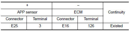
3.CHECK APP SENSOR 1 POWER SUPPLY CIRCUIT
- Turn ignition switch OFF.
- Disconnect ECM harness connector.
- Check the continuity between APP sensor harness connector and ECM harness connector
- Also check harness for short to ground.
Is the inspection result normal? YES >> Perform the trouble diagnosis for power supply circuit.
NO >> Repair or replace error-detected parts.
4.CHECK APP SENSOR 1 GROUND CIRCUIT
- Turn ignition switch OFF.
- Disconnect ECM harness connector.
- Check the continuity between APP sensor harness connector and ECM harness connector.
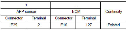
Also check harness for short to power.
Is the inspection result normal? YES >> GO TO 5.
NO >> Repair or replace error-detected parts.
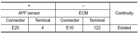
5.CHECK APP SENSOR INPUT SIGNAL CIRCUIT
- Check the continuity between APP sensor harness connector and ECM harness connector.
- Also check harness for short to ground and to power.
- Is the inspection result normal?
YES >> GO TO 6.
NO >> Repair or replace error-detected parts.
6.CHECK APP SENSOR
Check the APP sensor. Refer to EC-442, "Component Inspection".
Is the inspection result normal? YES >> GO TO 7.
NO >> Replace accelerator pedal assembly. Refer to ACC-3, "Removal and Installation".
7.CHECK INTERMITTENT INCIDENT
Refer to GI-41, "Intermittent Incident".
>> INSPECTION END
Component Inspection
1.CHECK ACCELERATOR PEDAL POSITION SENSOR
- Turn ignition switch OFF.
- Reconnect all harness connectors disconnected.
- Turn ignition switch ON.
- Check the voltage between ECM harness connector terminals as per the following condition.
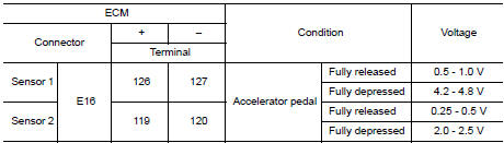
Is the inspection result normal? YES >> INSPECTION END
NO >> Replace accelerator pedal assembly. Refer to ACC-3, "Removal and Installation".
 P2119 electric throttle control actuator
DTC Description
DTC DETECTION LOGIC
DTC No.
CONSULT screen terms
(Trouble diagnosis content)
DTC detecting condition
P2119
ETC ACTR-B1
(Throttle actuator control throt ...
 P2127, P2128 APP sensor
DTC Description
DTC DETECTION LOGIC
DTC No.
CONSULT screen terms
(Trouble diagnosis content)
DTC detecting condition
P2127
APP SEN 2/CIRC
(Throttle/pedal position sens ...
Other materials:
Lights
Headlights
Replacing the halogen headlight bulb
(if so equipped)
The headlight is a semi-sealed beam type which
uses a replaceable headlight (halogen) bulb. Because
the headlight assembly must be removed
from the vehicle for bulb replacement, see your
NISSAN dealer.
CAUTION
...
Brake pedal vibration or operation sound occurs
Description
Brake pedal vibrates and motor sound from ABS actuator and electric unit
(control unit) occurs, when the
engine starts.
Brake pedal vibrates during braking.
CAUTION:
Vibration may be felt during brake pedal is lightly depressed (just placing a
foot on it) in the fo ...
Drive belt
QR25DE engine
Crankshaft pulley
Drive belt automatic tensioner pulley
Water pump pulley
Generator pulley
Air conditioner pulley
WARNINGBe sure the ignition switch is placed in the
OFF or LOCK position before servicing
drive belt. The engine cou ...
