Nissan Rogue Service Manual: P2101 electric throttle control function
DTC Description
DTC DETECTION LOGIC
| DTC No. | CONSULT screen terms (Trouble diagnosis content) | DTC detecting condition |
| P2101 | ETC FNCTN/CIRC-B1 (Throttle actuator ″A″ control motor circuit range/performance) | Electric throttle control function does not operate properly |
POSSIBLE CAUSE
- Harness or connectors (Throttle control motor circuit is open or shorted.)
- Electric throttle control actuator
FAIL-SAFE
ECM stops the electric throttle control actuator control, throttle valve is maintained at a fixed opening (approx.
5 degrees) by the return spring.
DTC CONFIRMATION PROCEDURE
1.CHECK DTC PRIORITY
If DTC P2101 is displayed with DTC P2100 or P2119, first perform the trouble diagnosis for DTC P2100 or P2119.
Is applicable DTC detected? YES >> Perform diagnosis of applicable. Refer to EC-93, "DTC Index".
NO >> GO TO 2.
2.PRECONDITIONING
If DTC Confirmation Procedure has been previously conducted, always perform the following procedure before conducting the next test.
- Turn ignition switch OFF and wait at least 10 seconds.
- Turn ignition switch ON.
- Turn ignition switch OFF and wait at least 10 seconds.
TESTING CONDITION: Before performing the following procedure, confirm that battery voltage is more than 11 V when engine is running.
>> GO TO 3.
3.PERFORM DTC CONFIRMATION PROCEDURE
- Turn ignition switch ON and wait at least 2 seconds.
- Start engine and let it idle for 5 seconds.
- Check DTC.
Is DTC detected? YES >> Proceed to EC-433, "Diagnosis Procedure".
NO >> INSPECTION END
Diagnosis Procedure
1.CHECK DTC PRIORITY
If DTC P2101 is displayed with DTC P2100 or P2119, first perform the trouble diagnosis for DTC P2100 or P2119.
Is applicable DTC detected? YES >> Perform diagnosis of applicable. Refer to EC-93, "DTC Index".
NO >> GO TO 2.
2.CHECK THROTTLE CONTROL MOTOR RELAY INPUT SIGNAL
Check the voltage between ECM harness connector terminals as per the following conditions.
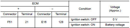
Is the inspection result normal? YES >> GO TO 5.
NO >> GO TO 3.
3.CHECK THROTTLE CONTROL MOTOR RELAY POWER SUPPLY CIRCUIT
- Check the continuity between ECM harness connector and IPDM E/R harness connector.
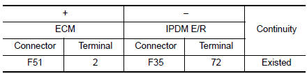
- Also check harness for short to ground.
Is the inspection result normal? YES >> GO TO 4.
NO >> Repair or replace error-detected parts.
4.CHECK THROTTLE CONTROL MOTOR RELAY INPUT SIGNAL CIRCUIT
- Turn ignition switch OFF.
- Disconnect ECM harness connector.
- Disconnect IPDM E/R harness connector.
- Check the continuity between ECM harness connector and IPDM E/R harness connector.
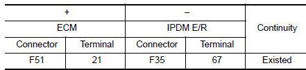
- Also check harness for short to ground and to power.
Is the inspection result normal? YES >> Perform the trouble diagnosis for power supply circuit.
NO >> Repair or replace error-detected parts.
5.CHECK THROTTLE CONTROL MOTOR OUTPUT SIGNAL CIRCUIT
- Turn ignition switch OFF.
- Disconnect electric throttle control actuator harness connector.
- Disconnect ECM harness connector.
- Check the continuity between electric throttle control actuator harness connector and ECM harness connector.
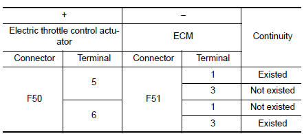
- Also check harness for short to ground and to power.
Is the inspection result normal? YES >> GO TO 6.
NO >> Repair or replace error-detected parts.
6.CHECK ELECTRIC THROTTLE CONTROL ACTUATOR VISUALLY
- Remove the intake air duct. Refer to EM-24, "Exploded View".
- Check if foreign matter is caught between the throttle valve and the housing.
Is the inspection result normal? YES >> GO TO 7.
NO >> Remove the foreign matter and clean the electric throttle control actuator inside, then perform throttle valve closed position learning. Refer to EC-140, "Work Procedure".
7.CHECK THROTTLE CONTROL MOTOR
Check the throttle control motor. Refer to EC-435, "Component Inspection".
Is the inspection result normal? YES >> GO TO 8.
NO >> Replace electric throttle control actuator. Refer to EM-26, "Removal and Installation".
8.CHECK INTERMITTENT INCIDENT
Refer to GI-41, "Intermittent Incident".
>> INSPECTION END
Component Inspection
1.CHECK THROTTLE CONTROL MOTOR
- Turn ignition switch OFF.
- Disconnect electric throttle control actuator harness connector.
- Check the resistance between electric throttle control actuator terminals as per the following.
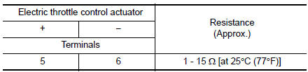
Is the inspection result normal? YES >> INSPECTION END
NO >> Replace electric throttle control actuator. Refer to EM-26, "Removal and Installation".
 P2100, P2103 throttle control motor relay
DTC Description
DTC DETECTION LOGIC
DTC No.
CONSULT screen terms
(Trouble diagnosis content)
DTC detecting condition
P2100
ETC MOT PWR-B1
(Throttle actuator ″A&# ...
 P2118 throttle control motor
DTC Description
DTC DETECTION LOGIC
DTC No.
CONSULT screen terms
(Trouble diagnosis content)
DTC detecting condition
P2118
ETC MOT-B1
(Throttle actuator control motor ...
Other materials:
Wiring diagram
CHASSIS CONTROL
Wiring Diagram
...
Precaution
Precaution for Supplemental Restraint System (SRS) "AIR BAG" and "SEAT
BELT
PRE-TENSIONER"
The Supplemental Restraint System such as “AIR BAG” and “SEAT BELT PRE-TENSIONER”,
used along
with a front seat belt, helps to reduce the risk or severity of injury to the
...
Precaution
Precaution for Supplemental Restraint System (SRS) "AIR BAG" and "SEAT
BELT
PRE-TENSIONER"
The Supplemental Restraint System such as “AIR BAG” and “SEAT BELT
PRE-TENSIONER”, used along
with a front seat belt, helps to reduce the risk or severity of injury to the
...
