Nissan Rogue Service Manual: P2100, P2103 throttle control motor relay
DTC Description
DTC DETECTION LOGIC
| DTC No. | CONSULT screen terms (Trouble diagnosis content) | DTC detecting condition |
| P2100 | ETC MOT PWR-B1 (Throttle actuator ″A″ control motor circuit/ open) | ECM detects a voltage of power source for throttle control motor is excessively low. |
| P2103 | ETC MOT PWR-B1 (Throttle actuator ″A″ control motor circuit high) | ECM detect the throttle control motor relay is stuck ON. |
POSSIBLE CAUSE
DTC P2100
- Harness or connectors (Throttle control motor relay circuit is open.)
- Throttle control motor relay
DTC P2103
- Harness or connectors (Throttle control motor relay circuit is shorted.)
- Throttle control motor relay
FAIL-SAFE
ECM stops the electric throttle control actuator control, throttle valve is maintained at a fixed opening (approx.
5 degrees) by the return spring.
DTC CONFIRMATION PROCEDURE
1.PRECONDITIONING
If DTC Confirmation Procedure has been previously conducted, always perform the following procedure before conducting the next test.
- Turn ignition switch OFF and wait at least 10 seconds.
- Turn ignition switch ON.
- Turn ignition switch OFF and wait at least 10 seconds.
TESTING CONDITION: Before performing the following procedure, confirm that battery voltage is more than 8 V.
Witch DTC is detected? P2100 >> GO TO 2.
P2103 >> GO TO 3.
2.PERFORM DTC CONFIRMATION PROCEDURE FOR DTC P2100
- Turn ignition switch ON and wait at least 2 seconds.
- Start engine and let it idle for 5 seconds.
- Check DTC.
Is DTC detected? YES >> Proceed to EC-431, "Diagnosis Procedure".
NO >> INSPECTION END
3.PERFORM DTC CONFIRMATION PROCEDURE FOR DTC P2103
- Turn ignition switch ON and wait at least 1 second.
- Check DTC.
Is DTC detected? YES >> Proceed to EC-431, "Diagnosis Procedure".
NO >> INSPECTION END
Diagnosis Procedure
1.CHECK THROTTLE CONTROL MOTOR RELAY POWER SUPPLY
- Turn ignition switch OFF.
- Check the voltage between ECM harness connector and ground.
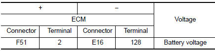
Is the inspection result normal? YES >> GO TO 3.
NO >> GO TO 2.
2.CHECK THROTTLE CONTROL MOTOR RELAY POWER SUPPLY CIRCUIT
- Disconnect ECM harness connector.
- Disconnect IPDM E/R harness connector.
- Check the continuity between ECM harness connector and IPDM E/R harness connector.
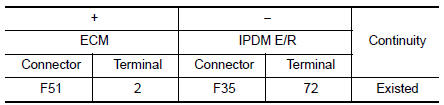
- Also check harness for short to ground.
Is the inspection result normal? YES >> Perform the trouble diagnosis for power supply circuit.
NO >> Repair or replace error-detected parts.
3.CHECK THROTTLE CONTROL MOTOR RELAY INPUT SIGNAL
Check the voltage between ECM harness connector and ground as per the following conditions.
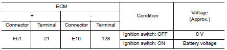
Is the inspection result normal? YES >> GO TO 5.
NO >> GO TO 4.
4.CHECK THROTTLE CONTROL MOTOR RELAY INPUT SIGNAL CIRCUIT
- Turn ignition switch OFF.
- Disconnect ECM harness connector.
- Disconnect IPDM E/R harness connector.
- Check the continuity between ECM harness connector and IPDM E/R harness connector.
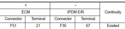
- Also check harness for short to ground and to power.
Is the inspection result normal? YES >> GO TO 5.
NO >> Repair or replace error-detected parts.
5.CHECK INTERMITTENT INCIDENT
Refer to GI-41, "Intermittent Incident".
>> INSPECTION END
 P2096, P2097 A/F sensor 1
DTC Description
DTC DETECTION LOGIC
DTC No.
CONSULT screen terms
(Trouble diagnosis content)
DTC detecting condition
P2096
POST CATALYST FUEL TRIM SYS B1
(Post catalys ...
 P2101 electric throttle control function
DTC Description
DTC DETECTION LOGIC
DTC No.
CONSULT screen terms
(Trouble diagnosis content)
DTC detecting condition
P2101
ETC FNCTN/CIRC-B1
(Throttle actuator ″ ...
Other materials:
Vehicle phonebook
To access the vehicle phonebook:
Press the button on
the control panel.
Touch the “Phonebook” key.
Choose the desired entry from the displayed
list.
The number of the entry will be displayed on
the screen. Touch the number to initiate dialing.
NOTE:
...
Symptom diagnosis
NISSAN VEHICLE IMMOBILIZER SYSTEM-NATS SYMPTOMS
Symptom Table
NOTE:
Before performing the diagnosis in the following table, check
“SEC-150, "Work Flow"”.
Check that vehicle is under the condition shown in “Conditions
of vehicle” before starting diagnosis, ...
B0092 rear side air bag satellite sensor LH
Description
DTC B0092 REAR SATELLITE SENSOR LH
The rear side air bag satellite sensor LH is wired to the air bag diagnosis
sensor unit. The air bag diagnosis
sensor unit will monitor the rear side air bag satellite sensor LH for internal
failures and its circuits for communication
errors.
P ...
