Nissan Rogue Service Manual: P0335 CKP sensor (POS)
DTC Description
DTC DETECTION LOGIC
| DTC No. | CONSULT screen terms (Trouble diagnosis content) | DTC detecting conditio |
| P0335 | CKP SEN/CIRCUIT (Crankshaft position sensor ″A″ circuit) |
|
POSSIBLE CAUSE
- Harness or connectors [Crankshaft position sensor (POS) circuit is open or shorted.]
- Crankshaft position sensor (POS)
- Signal plate
- Sensor power supply 2 circuit
FAIL-SAFE
Not applicable
DTC CONFIRMATION PROCEDURE
1.CHECK DTC PRIORITY
If DTC P0335 is displayed with DTC P0643, first perform the trouble diagnosis for DTC P0643.
Is applicable DTC detected? YES >> Perform diagnosis of applicable. Refer to EC-379, "DTC Description".
NO >> GO TO 2.
2.PRECONDITIONING
If DTC Confirmation Procedure has been previously conducted, always perform the following procedure before conducting the next test.
- Turn ignition switch OFF and wait at least 10 seconds.
- Turn ignition switch ON.
- Turn ignition switch OFF and wait at least 10 seconds.
TESTING CONDITION: Before performing the following procedure, confirm that battery voltage is more than 10.5 V with ignition switch ON.
>> GO TO 3.
3.PERFORM DTC CONFIRMATION PROCEDURE
- Start engine and let it idle for at least 5 seconds.
If engine does not start, crank engine for at least 2 seconds.
- Check 1st trip DTC.
Is 1st trip DTC detected? YES >> Proceed to EC-295, "Diagnosis Procedure".
NO >> INSPECTION END
Diagnosis Procedure
1.CHECK DTC PRIORITY
If DTC P0335 is displayed with DTC P0643, first perform the trouble diagnosis for DTC P0643.
Is applicable DTC detected? YES >> Perform diagnosis of applicable. Refer to EC-379, "DTC Description".
NO >> GO TO 2.
2.CHECK CRANKSHAFT POSITION (CKP) SENSOR (POS) POWER SUPPLY
- Disconnect crankshaft position (CKP) sensor (POS) harness connector.
- Turn ignition switch ON.
- Check the voltage between CKP sensor (POS) harness connector and ground.
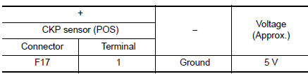
Is the inspection result normal? YES >> GO TO 4.
NO >> GO TO 3.
3.CHECK CKP SENSOR (POS) GROUND CIRCUIT
- Turn ignition switch OFF.
- Disconnect ECM harness connector.
- Check the continuity between CKP sensor (POS) harness connector and ECM harness connector.
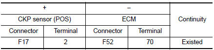
- Also check harness for short to power.
Is the inspection result normal? YES >> GO TO 4.
NO >> Repair or replace error-detected parts.
4.CHECK CKP SENSOR (POS) INPUT SIGNAL CIRCUIT
- Check the continuity between CKP sensor (POS) harness connector and ECM harness connector.
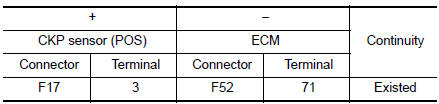
- Also check harness for short to ground and to power.
Is the inspection result normal? YES >> GO TO 5.
NO >> Repair or replace error-detected parts.
5.CHECK CRANKSHAFT POSITION SENSOR (POS)
Check the crankshaft position sensor (POS). Refer to EC-297, "Component Inspection (Crankshaft Position sensor)".
Is the inspection result normal? YES >> GO TO 6.
NO >> Replace crankshaft position sensor (POS). Refer to EM-92, "Exploded View".
6.CHECK GEAR TOOTH
- Remove crankshaft position sensor (POS). Refer to EM-92, "Exploded View".
- Look into the mounting hole A of the crankshaft position sensor (POS) to check that there is no missing gear tooth in the signal plate 1.
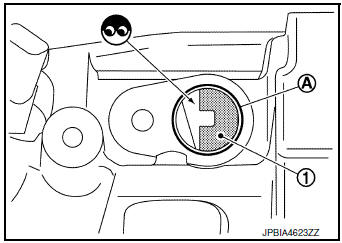
Is the inspection result normal? YES >> GO TO 7.
NO >> Replace the signal plate. Refer to EM-92, "Exploded View".
7.CHECK INTERMITTENT INCIDENT
Refer to GI-41, "Intermittent Incident".
>> INSPECTION END
Component Inspection (Crankshaft Position sensor)
1.CHECK CRANKSHAFT POSITION SENSOR (POS)-1
- Turn ignition switch OFF.
- Loosen the fixing bolt of the sensor.
- Disconnect crankshaft position sensor (POS) harness connector.
- Remove the sensor.
- Visually check the sensor for chipping.
Is the inspection result normal? YES >> GO TO 2.
NO >> Replace crankshaft position sensor (POS). Refer to EM- 92, "Exploded View".
2.CHECK CRANKSHAFT POSITION SENSOR (POS)-2
Check the resistance between crankshaft position sensor (POS) terminals as per the following.
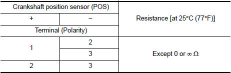
the inspection result normal? YES >> INSPECTION END
NO >> Replace crankshaft position sensor (POS). Refer to EM-92, "Exploded View".
 P0327, P0328 KS
DTC Description
DTC DETECTION LOGIC
DTC No.
CONSULT screen terms
(Trouble diagnosis content)
DTC detecting condition
P0327
KNOCK SEN/CIRC-B1
(Knock sensor 1 circuit lo ...
 P0340 CMP sensor (phase)
DTC Description
DTC DETECTION LOGIC
DTC No.
CONSULT screen terms
(Trouble diagnosis content)
DTC detecting cond
P0340
CMP SEN/CIRC-B1
(Camshaft position sensor ″ ...
Other materials:
Power window motor
DRIVER SIDE
DRIVER SIDE : Description
Door glass moves UP/DOWN by receiving the signal from main power window and
door lock/unlock switch.
DRIVER SIDE : Component Function Check
1. CHECK FRONT POWER WINDOW MOTOR LH OPERATION
Check front power window motor LH operation with main power window a ...
C1770, C1771, C1772, C1773 G sensor
DTC Description
DTC DETECTION LOGIC
DTC
Display Item
Malfunction Detected Condition
Possible Causes
C1770
G SENSOR FL
(G sensor front left)
Malfunction in the G sensor data from front left wheel sensor.
Tire pressure sensor
Tire pressure rece ...
Removal and installation
AV CONTROL UNIT
Exploded View
AV control unit bracket (LH)
AV control unit
AV control unit bracket (RH)
Removal and Installation
REMOVAL
CAUTION:
Before disconnecting the AV control unit and battery terminals,
turn the ignition switch OFF and wait
at least 30 secon ...
