Nissan Rogue Service Manual: P0102, P0103 MAF sensor
DTC Description
DTC DETECTION LOGIC
| DTC No. | CONSULT screen terms (Trouble diagnosis content) | DTC detecting condition |
| P0102 | MAF SEN/CIRCUIT-B1 (Mass or volume air flow ″A″ circuit low) | An excessively low voltage from the mass air flow sensor is sent to ECM. |
| P0103 | MAF SEN/CIRCUIT-B1 (Mass or volume air flow ″A″ circuit high) | An excessively high voltage from the mass air flow sensor is sent to ECM. |
POSSIBLE CAUSE
DTC P0102
- Harness or connectors (Mass air flow sensor circuit is open or shorted.)
- Intake air leaks
- Mass air flow sensor
- Sensor power supply 2 circuit
DTC P0103
- Harness or connectors (Mass air flow sensor circuit is open or shorted.)
- Mass air flow sensor
- Sensor power supply 2 circuit
FAIL-SAFE
- Traveling control mode (Accelerator angle variation control)
- Traveling control mode (Engine output control)
- Device fix mode
DTC CONFIRMATION PROCEDURE
1.PRECONDITIONING
If DTC Confirmation Procedure has been previously conducted, always perform the following procedure before conducting the next test.
- Turn ignition switch OFF and wait at least 10 seconds.
- Turn ignition switch ON.
- Turn ignition switch OFF and wait at least 10 seconds.
Which DTC is detected? P0102 >> GO TO 2.
P0103 >> GO TO 3.
2.PERFORM DTC CONFIRMATION PROCEDURE FOR DTC P0102
- Start engine and wait at least 5 seconds.
- Check DTC.
Is DTC detected? YES >> Proceed to EC-203, "Diagnosis Procedure".
NO >> INSPECTION END
3.PERFORM DTC CONFIRMATION PROCEDURE FOR DTC P0103-1
- Turn ignition switch ON and wait at least 5 seconds.
- Check DTC.
Is DTC detected? YES >> Proceed to EC-203, "Diagnosis Procedure".
NO >> GO TO 4.
4.PERFORM DTC CONFIRMATION PROCEDURE FOR DTC P0103-2
- Start engine and wait at least 5 seconds.
- Check DTC.
Is DTC detected? YES >> Proceed to EC-203, "Diagnosis Procedure".
NO >> INSPECTION END
Diagnosis Procedure
1.INSPECTION START
Confirm the detected DTC.
Which DTC is detected? P0102 >> GO TO 2.
P0103 >> GO TO 3.
2.CHECK INTAKE SYSTEM
Check the following for connection.
- Air duct
- Vacuum hoses
- Intake air passage between air duct to intake manifold
Is the inspection result normal? YES >> GO TO 3.
NO >> Reconnect the parts. Refer to EM-24, "Exploded View".
3.CHECK MAF SENSOR POWER SUPPLY
- Turn ignition switch OFF.
- Disconnect mass air flow (MAF) sensor harness connector.
- Turn ignition switch ON.
- Check the voltage between MAF sensor harness connector and ground.
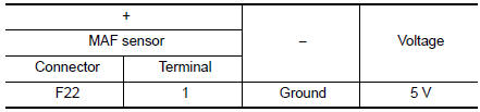
Is the inspection result normal? YES >> GO TO 5.
NO >> GO TO 4.
4.CHECK SENSOR POWER SUPPLY 2 CIRCUIT
Perform EC-484, "Diagnosis Procedure".
Is the inspection result normal? YES >> Perform the trouble diagnosis for power supply circuit.
NO >> Repair or replace error-detected parts.
5.CHECK MAF SENSOR GROUND CIRCUIT
- Turn ignition switch OFF.
- Disconnect ECM harness connector.
- Check the continuity between MAF sensor harness connector and ECM harness connector.
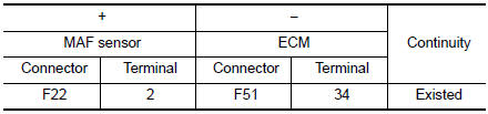
Is the inspection result normal? YES >> GO TO 6.
NO >> Repair or replace error-detected parts.
6.CHECK MAF SENSOR INPUT SIGNAL CIRCUIT
- Check the continuity between MAF sensor harness connector and ECM harness connector.
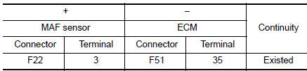
- Also check harness for short to ground and to power.
Is the inspection result normal? YES >> GO TO 7.
NO >> Repair open circuit or short to ground or short to power in harness or connectors.
7.CHECK MAF SENSOR
Check the MAF sensor. Refer to EC-200, "Component Inspection".
Is the inspection result normal? YES >> GO TO 8.
NO >> Replace mass air flow sensor. Refer to EM-24, "Exploded View".
8.CHECK INTERMITTENT INCIDENT
Refer to GI-41, "Intermittent Incident".
>> INSPECTION END
Component Inspection
1.CHECK MASS AIR FLOW SENSOR-1
 With CONSULT
- Turn ignition switch OFF.
- Reconnect all harness connectors disconnected.
- Start engine and warm it up to normal operating temperature.
- Connect CONSULT and select “DATA MONITOR” mode of “ENGINE”.
- Select “MASS AIR FLOW SENSOR (Hz)” and check indication.
| Monitor item | Condition | Value |
| MASS AIR FLOW SENSOR (Hz) | Ignition switch ON (Engine stopped.) | Approx. 3500 Hz |
| Idle (Engine is warmed-up to normal operating temperature.) | 3500- 4100 Hz | |
| 2,500 rpm (Engine is warmed-up to normal operating temperature.) | 5000 - 5600 Hz | |
| Idle to about 4,000 rpm | 3500 - 4100 Hz to Approx. 6300 Hz* |
*: Check for linear frequency rise in response to engine being increased to about 4,000 rpm.
Is the inspection result normal? YES >> INSPECTION END
NO >> GO TO 2.
2.CHECK FOR THE CAUSE OF UNEVEN AIR FLOW THROUGH MASS AIR FLOW SENSOR
- Turn ignition switch OFF.
- Check for the cause of uneven air flow through mass air flow sensor. Refer to the following.
- Crushed air ducts
- Malfunctioning seal of air cleaner element
- Uneven dirt of air cleaner element
- Intake valve deposits
- Improper specification of intake air system parts
Is the inspection result normal? YES >> GO TO 4.
NO >> GO TO 3.
3.CHECK MASS AIR FLOW SENSOR-2
 With CONSULT
- Repair or replace malfunctioning part.
- Start engine and warm it up to normal operating temperature.
- Connect CONSULT and select “DATA MONITOR” mode of “ENGINE”.
- Select “MASS AIR FLOW SENSOR (Hz)” and check indication.
| Monitor item | Condition | Value |
| MASS AIR FLOW SENSOR (Hz) | Ignition switch ON (Engine stopped.) | Approx. 3500 Hz |
| Idle (Engine is warmed-up to normal operating temperature.) | 3500- 4100 Hz | |
| 2,500 rpm (Engine is warmed-up to normal operating temperature.) | 5000 - 5600 Hz | |
| Idle to about 4,000 rpm | 3500 - 4100 Hz to Approx. 6300 Hz* |
*: Check for linear frequency rise in response to engine being increased to about 4,000 rpm.
Is the inspection result normal? YES >> INSPECTION END
NO >> GO TO 4.
4.CHECK MASS AIR FLOW SENSOR-3
With CONSULT
- Turn ignition switch OFF.
- Disconnect mass air flow sensor harness connector and reconnect it again.
- Start engine and warm it up to normal operating temperature.
- Connect CONSULT and select “DATA MONITOR” mode of “ENGINE”.
- Select “MASS AIR FLOW SENSOR (Hz)” and check indication.
| Monitor item | Condition | Value |
| MASS AIR FLOW SENSOR (Hz) | Ignition switch ON (Engine stopped.) | Approx. 3500 Hz |
| Idle (Engine is warmed-up to normal operating temperature.) | 3500- 4100 Hz | |
| 2,500 rpm (Engine is warmed-up to normal operating temperature.) | 5000 - 5600 Hz | |
| Idle to about 4,000 rp | 3500 - 4100 Hz to Approx. 6300 Hz* |
*: Check for linear frequency rise in response to engine being increased to about 4,000 rpm.
Is the inspection result normal? YES >> INSPECTION END
NO >> Clean or replace mass air flow sensor. Refer to EM-24, "Exploded View".
 P0101 MAF sensor
DTC Description
DTC DETECTION LOGIC
DTC No.
CONSULT screen terms
(Trouble diagnosis content)
DTC detecting condition
P0101
MAF SEN/CIRCUIT-B1
(Mass or volume air Flow ...
 P0111 IAT sensor
DTC Description
DTC DETECTION LOGIC
DTC No.
CONSULT screen terms
(Trouble diagnosis content)
DTC detecting condition
P0111
IAT SENSOR 1 B1
(Intake air temperature sens ...
Other materials:
Brake pedal vibration or operation sound occurs
Description
Brake pedal vibrates and motor sound from ABS actuator and electric unit
(control unit) occurs, when the
engine starts.
Brake pedal vibrates during braking.
CAUTION:
Vibration may be felt during brake pedal is lightly depressed (just placing a
foot on it) in the fo ...
Control panel buttons — color screen with Navigation System (if so equipped)
Control panel buttons — color screen with Navigation System
MAP button*
Display screen
button**
button
(brightness control)
button
BACK button
ENTER / AUDIO button / TUNE / SCROLL
knob
POWER button / VOLUME control knob
CAM ...
Unit removal and installation
ENGINE ASSEMBLY
Exploded view
Engine mounting insulator (RH)
Upper torque rod (RH)
Engine mounting bracket (RH)
Lower torque rod
Torque rod bracket
Engine mounting insulator (LH)
Removal and installation (FWD)
WARNING:
Situate the vehicl ...
