Nissan Rogue Service Manual: Lower link
Exploded View
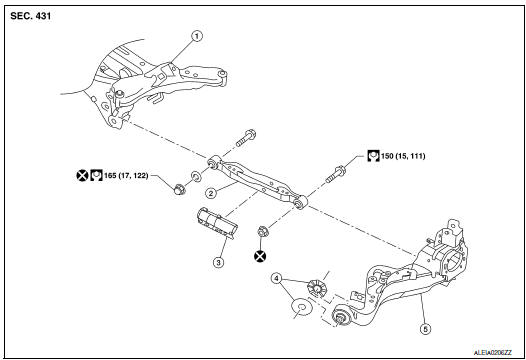
- Rear suspension member
- Lower link
- Lower link deflector
- Rubber washer (LH/RH)
- Rear suspension arm
 Front
Front
Removal and Installation
REMOVAL
- Remove wheel and tire using power tool. Refer to WT-60, "Exploded View".
- Remove connecting rod. Refer to RSU-21, "Exploded View".
- Remove rear height sensor (if equipped). Refer to EXL-271, "Removal and Installation - Rear Height Sensor".
- Set suitable jack under rear suspension arm to relieve the coil spring tension.
- Remove lower link, nut, and bolt from rear suspension arm with power tool.
- Remove lower link, nut, washer, and bolt from rear suspension member with power tool.
- Remove lower link protector (if necessary).
- Perform the inspection after removal. Refer to RSU-17, "Inspection".
INSTALLATION
Installation is in the reverse order of removal.
- Perform final tightening of rear suspension member and axle installation position under unladen conditions with tires on level ground.
- After installation, perform headlamp initialization. Refer to EXL-223, "Diagnosis Procedure".
- Adjust the neutral position of the steering angle sensor. Refer to BRC-70, "Work Procedure".
- Perform the inspection after installation. Refer to RSU-17, "Inspection".
Inspection
INSPECTION AFTER REMOVAL
Check lower link and bushing for any deformation, cracks, or damage. Replace it if necessary.
INSPECTION AFTER INSTALLATION
Check wheel alignment. Refer to RSU-6, "Inspection".
 Rear suspension ARM
Exploded View
Rear suspension arm
Rubber washer (LH/RH)
Rear suspension arm bracket
Rear suspension arm stay
Front
Removal and Installation
REMOVAL
Remove the wheel hu ...
 Upper link
Exploded View
Rear suspension member
Upper link
Rubber washer (LH/RH)
Rear suspension arm
Front
Removal and Installation
REMOVAL
Remove wheel and tir ...
Other materials:
Removal and installation
REAR WHEEL HUB
Exploded View
Suspension arm
Back plate
Wheel stud
Wheel hub and bearing
Disc brake rotor
Plug
Removal and Installation
REMOVAL
Wheel Hub and Bearing
Remove the wheel and tire using power tool. Refer to WT-57,
"Adjustment".
Remove t ...
Basic inspection
DIAGNOSIS AND REPAIR WORKFLOW
Work Flow (With GR8-1200 NI)
STARTING SYSTEM DIAGNOSIS WITH GR8-1200 NI
To test the starting system, use the following special service tool:
GR8-1200 NI Multitasking battery and electrical diagnostic station
NOTE:
Refer to the diagnostic station Instruc ...
P0448 EVAP canister vent control valve
DTC Description
DTC DETECTION LOGIC
DTC No.
CONSULT screen terms
(Trouble diagnosis content)
DTC detecting condition
P0448
VENT CONTROL VALVE
(Evaporative emission system vent control
circuit shorted)
EVAP canister vent control valve remains closed under specif ...
