Nissan Rogue Service Manual: Key switch signal circuit (without intelligent key)
Description
Transmits a key switch signal to the BCM.
Component Function Check
1. CHECK BCM INPUT SIGNAL
Select "Data Monitor" for "BCM" and check the "KEY ON SW" monitor value.
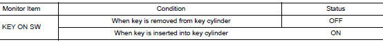
Is the inspection result normal? YES >> Inspection End.
NO >> Refer to WCS-47, "Diagnosis Procedure".
Diagnosis Procedure
Regarding Wiring Diagram information, refer to WCS-29, "Wiring Diagram".
1. CHECK BCM INPUT SIGNAL
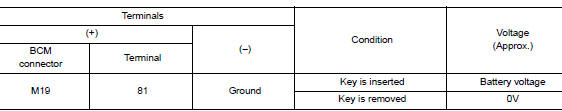
Check voltage between BCM harness connector M19 terminal 81 and ground.
Is the inspection result normal? YES >> Inspection End.
NO >> GO TO 2.
2. CHECK KEY SWITCH CIRCUIT
- Disconnect BCM connector M19 and key switch.
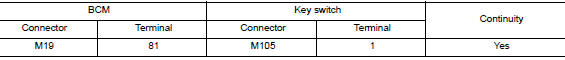
- Check continuity between BCM harness connector M19 terminal 81 and key switch harness connector M105 terminal 1.
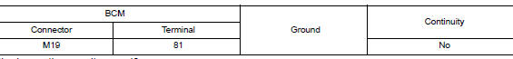
- Check continuity between BCM harness connector M19 terminal 81 and ground.
Is the inspection result normal? YES >> GO TO 3.
NO >> Repair or replace harness or connector.
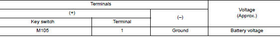
3. CHECK KEY SWITCH POWER SUPPLY CIRCUIT
Check voltage between key switch harness connector M105 terminal 1 and ground.
Is the inspection result normal? YES >> GO TO 4.
NO >> Repair or replace harness or connector.
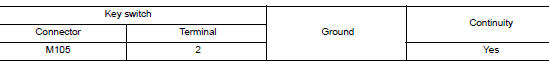
4. CHECK KEY SWITCH GROUND CIRCUIT
Check continuity between key switch harness connector M105 terminal 2 and ground.
Is the inspection result normal? YES >> Replace key switch.
NO >> Repair or replace harness or connector.
Component Inspection
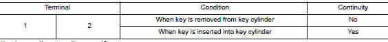
1. CHECK KEY SWITCH
- Turn ignition switch OFF.
- Disconnect key switch.
- Check continuity between key switch terminals 1 and 2.
Is the inspection result normal? YES >> Inspection End.
NO >> Replace key switch.
 Parking brake switch signal circuit
Component Function Check
1.CHECK PARKING BRAKE SWITCH OPERATION
Check that brake warning lamp in combination meter turns ON/OFF when parking
brake is actuated.
Is the inspection result normal?
...

Other materials:
Diagnosis system (TCM)
DIAGNOSIS DESCRIPTION
DIAGNOSIS DESCRIPTION : 1 Trip Detection Diagnosis and 2 Trip Detection
Diagnosis
NOTE:
“Start the engine and turn OFF the ignition switch after warm-up.” This is
defined as 1 trip.
1 TRIP DETECTION DIAGNOSIS
When initial malfunction is detected, TCM memorizes DTC. ...
Diagnosis system [ABS actuator and electric unit (control
unit)]
CONSULT Function
APPLICATION ITEMS
CONSULT can display each diagnostic item using the diagnostic test modes as
follows.
Mode
Function description
ECU identification
Parts number of ABS actuator and electric unit (control unit) can be
read.
Self Diagnos ...
Air conditioner operation
Start the engine, turn the fan control dial to the
desired position, and press the
button to
activate the air conditioner. When the air conditioner
is on, cooling and dehumidifying functions
are added to the heater operation.
The air conditioner cooling function operates
only when the engin ...
