Nissan Rogue Owners Manual: Instrument panel
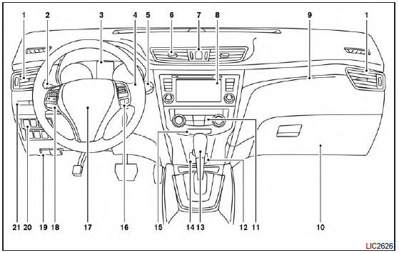
- Vent
- Headlight/fog light (if so equipped)/turn signal switch
- Meters, gauges, warning/indicator lights and Vehicle Information Display
- Windshield wiper/washer switch and rear window wiper/washer switch /Ignition switch (if so equipped)
- Push-button ignition switch (if so equipped)
- Vent
- Hazard warning flasher switch
- Radio /Navigation system* (if so equipped)
- . Front passenger supplemental air bag
- Glove box
- Heater and air conditioning controls
- Power outlet
- Shift lever
- Auxiliary jack /USB port
- Front passenger air bag status light
- Cruise control main/set switches (/Bluetooth Hands-Free Phone System (if so equipped)
- Driver supplemental air bag/Horn (, )
- Control panel and Vehicle Information Display switches
- Hood release /Fuel door release
- Vehicle Dynamic Control (VDC) OFF switch Sport mode switch ECO mode switch (if so equipped) Power liftgate switch (if so equipped) (P.3-28) Power liftgate main switch (if so equipped) Warning systems switch (if so equipped) All-Wheel Drive (AWD) lock switch (if so equipped) Hill descent control switch (if so equipped)
- Instrument brightness control /Twin trip odometer reset switch
*: Refer to the separate Navigation System Owner’s Manual (if so equipped).
Refer to the page number indicated in parentheses for operating details.

 Meters and gauges
Tachometer
Warning/indicator lights
Vehicle Information Display/Odometer/
Twin trip odometer
Speedometer
Fuel gauge
Engine coolant temperature gauge
...
Other materials:
Preparation
Special Service Tools
The actual shapes of TechMate tools may differ from those of special service
tools illustrated here.
Tool number
(TechMate No.)
Tool name
Description
KV38100200
(J-26233)
Drift
a: 65 mm (2.56 in) dia.
b: 49 mm (1.93 in) dia.
...
B00A0 OCS system
Description
DTC B1017, B1018, B1020, B1021, B1022, B1025, B1032, B1048 OCCUPANT
CLASSIFICATION
SYSTEM (OCS)
The OCS control unit is wired to the air bag diagnosis sensor unit. The air
bag diagnosis sensor unit will monitor
the OCS for failures and interruptions in communication between the O ...
System description
SYSTEM
System Description
SYSTEM DIAGRAM
SYSTEM DESCRIPTION
The BCM has a CAN gateway function.
The BCM communicates between two CAN communication circuits.
The BCM selects and transmits only necessary information.
DIAGNOSIS SYSTEM (CAN GATEWAY)
CONSULT Function
...
