Nissan Rogue Service Manual: How to check terminal
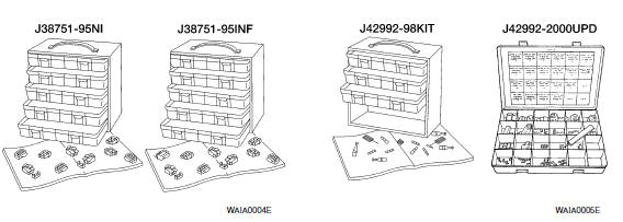
CONNECTOR AND TERMINAL PIN KIT
- Use the connector and terminal pin kits listed below when replacing connectors or terminals.
- The connector and terminal pin kits contain some of the most commonly used NISSAN/INFINITI connectors and terminals. For detailed connector and terminal pin replacement procedures, refer to the latest NISSAN/ INFINITI CONNECTOR AND TERMINAL PIN SERVICE MANUAL.
|
Tool number (Kent-Moore No.) Tool name |
Description |
| - (J38751-95NI) Connector and terminal pin kit (NISSAN) - (J38751-95INF) Connector and terminal pin kit (INFINITI) - (J42992-98KIT) OBD and terminal repair kit - (J42992-2000UPD) OBD-II Connector Kit Update |
 |
HOW TO PROBE CONNECTORS
- Connector damage and an intermittent connection can result from improperly probing of the connector during circuit checks.
- The probe of a digital multimeter (DMM) may not correctly fit the connector cavity. To correctly probe the connector, follow the procedures below using a “T” pin. For the best contact grasp the “T” pin using an alligator clip.
Probing from Harness Side
Standard type (not waterproof type) connector should be probed from harness side with “T” pin.
- If the connector has a rear cover such as a ECM connector, remove the rear cover before probing the terminal.
- Do not probe waterproof connector from harness side. Damage to the seal between wire and connector may result.
Probing from Terminal Side
FEMALE TERMINAL
- There is a small notch above each female terminal. Probe each
terminal with the “T” pin through the notch.
Do not insert any object other than the same type male terminal into female terminal.
- Some connectors do not have a notch above each terminal. To probe each terminal, remove the connector retainer to make contact space for probing.
MALE TERMINAL
- Carefully probe the contact surface of each terminal using a “T” pin.
CAUTION: Dot not bend terminal.
How to Check Enlarged Contact Spring of Terminal
- An enlarged contact spring of a terminal may create intermittent signals in the circuit.
- If the intermittent open circuit occurs, follow the procedure below to inspect for open wires and enlarged contact spring of female terminal.
- Assemble a male terminal and approx. 10 cm (3.9 in) of wire.
NOTE: Use a male terminal which matches the female terminal.
- Disconnect the suspected faulty connector and hold it terminal side up.
- While holding the wire of the male terminal, try to insert the male terminal into the female terminal.
CAUTION: Do not force the male terminal into the female terminal with your hands.

- While moving the connector, check whether the male terminal can be easily inserted or not.
- If the male terminal can be easily inserted into the female terminal, replace the female terminal.
Waterproof Connector Inspection
If water enters the connector, it can short interior circuits. This may lead to intermittent problems.
Check the following items to maintain the original waterproof characteristics.
RUBBER SEAL INSPECTION
- Most waterproof connectors are provided with a rubber seal between the male and female connectors. If the seal is missing, the waterproof performance may not meet specifications.
- The rubber seal may come off when connectors are disconnected.
Whenever connectors are reconnected, make sure the rubber seal is properly installed on either side of male or female connector.
WIRE SEAL INSPECTION
- The wire seal must be installed on the wire insertion area of a waterproof connector. Be sure that the seal is installed properly.
Terminal Lock Inspection
Check for unlocked terminals by pulling wire at the end of connector.
An unlocked terminal may create intermittent signals in the circuit.
 Basic inspection
SERVICE INFORMATION FOR ELECTRICAL INCIDENT
Work flow
STEP
DESCRIPTION
STEP 1
Get detailed information about the conditions and the
environment when the incident occurred ...
 Intermittent incident
DESCRIPTION
Sometimes the symptom is not present when the vehicle is brought in for
service. If possible, re-create the
conditions present at the time of the incident. Doing so may help avoid a No ...
Other materials:
P1226 TP sensor
DTC Description
DTC DETECTION LOGIC
DTC No.
CONSULT screen terms
(Trouble diagnosis content)
DTC detecting condition
P1226
CTP LEARNING-B1
(CTP LEARNING-B1)
Closed throttle position learning is not performed successfully,
repeatedly
POSSIBLE CAUSE
Elect ...
B0021 side curtain air bag module IH
DTC Logic
DTC DETECTION LOGIC
CONSULT name
DTC
DTC detecting condition
Repair order
CURTAIN AIRBAG MODULE LH CIRCUIT
[OPEN]
B0021
LH side curtain air bag module circuit
is open.
Refer to SRC-55, "Diagnosis Procedure".
CURTA ...
Removal and installation
EXHAUST SYSTEM
Exploded View
Exhaust diffuser
Muffler assembly
Mounting rubber
Mounting rubber
Mounting rubber
Ring gasket
Front exhaust tube
Mounting rubber
Exhaust gasket
Oxygen sensor 2
Center exhaust tube
Catalyst shroud
...
