Nissan Rogue Owners Manual: Heater and Air Conditioner (automatic) (if so equipped)
Heater and Air Conditioner
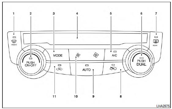
 (front defroster) button
- Temperature control dial (driver’s side) / ON-OFF button
- MODE (manual air flow control) button
- Display screen
- A/C (air conditioner) button
- Temperature control dial (passenger’s side)/DUAL (passenger’s side temperature control) button
-
 (rear window and
outside mirror
(if so equipped) defroster) button
(rear window and
outside mirror
(if so equipped) defroster) button -
 Fresh air intake
button
Fresh air intake
button - AUTO (automatic mode) button
-
 (fan speed control)
buttons
(fan speed control)
buttons -
 Air recirculation
button
Air recirculation
button
WARNING
|
NOTE:
- Odors from inside and outside the vehicle can build up in the air conditioner unit. Odor can enter the passenger compartment through the vents.
- When parking, set the heater and air conditioner
controls to turn off air recirculation to
allow fresh air into the passenger compartment.
This should help reduce odors inside the vehicle.
 Air flow charts
The following charts show the button and dial
positions for MAXIMUM AND QUICK heating,
cooling or defrosting. The air recirculation indicator
should always be in the OFF position
for heating and d ...
 Automatic operation
Cooling and/or dehumidified heating
(AUTO)
This mode may be used all year round as the
system automatically works to keep a constant
temperature. Air flow distribution and fan speed
are also cont ...
Other materials:
Radio
With the ignition placed in the ACC or ON position,
press the or POWER
button/VOLUME control knob to turn the radio
on. If you listen to the radio with the engine not
running, the ignition should be placed in the ACC
position.
Radio reception is affected by station signal
strength, distance ...
Ignition switch (if so equipped)
WARNING
Never remove or turn the key to the
LOCK position while driving. The steering
wheel will lock (for models with a
steering lock mechanism). This may
cause the driver to lose control of the
vehicle and could result in serious vehicle
damage or personal ...
Head restraints/Headrests
WARNINGHead restraints/headrests supplement
the other vehicle safety systems. They may
provide additional protection against injury
in certain rear end collisions. Adjustable
head restraints/headrests must be
adjusted properly, as specified in this section.
Check the adjus ...
