Nissan Rogue Service Manual: Fuel pump
Description
| Sensor | Input signal to ECM | ECM Function | Actuator |
| Crankshaft position sensor (POS) Camshaft position sensor (PHASE) |
Engine speed* | Fuel pump control | Fuel pump relay ↓ Fuel pump |
| Battery | Battery voltage* |
*: ECM determines the start signal status by the signals of engine speed and battery voltage.
The ECM activates the fuel pump for several seconds after the ignition switch is turned ON to improve engine start ability. If the ECM receives a engine speed signal from the camshaft position sensor (PHASE), it knows that the engine is rotating, and causes the pump to operate. If the engine speed signal is not received when the ignition switch is ON, the engine stalls. The ECM stops pump operation and prevents battery discharging, thereby improving safety. The ECM does not directly drive the fuel pump. It controls the ON/OFF fuel pump relay, which in turn controls the fuel pump.
| Condition | Fuel pump operation |
| Ignition switch is turned to ON | Operates for 1 second. |
| Engine running and cranking | Operates. |
| When engine is stopped | Stops in 1.5 seconds. |
| Except as shown above | Stops. |
Component Function Check
1.CHECK FUEL PUMP FUNCTION
- Turn ignition switch ON.
- Pinch fuel feed hose with two fingers.
Fuel pressure pulsation should be felt on the fuel feed hose for 1 second after ignition switch is turned ON.
Is the inspection result normal? YES >> INSPECTION END
NO >> Proceed to EC-467, "Diagnosis Procedure".
Diagnosis Procedure
1.CHECK FUEL PUMP RELAY CONTROL SIGNAL
- Turn ignition switch ON.
- Check the voltage between ECM harness connector.
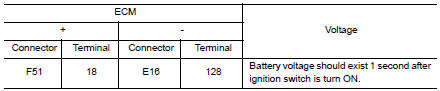
Is the inspection result normal? YES >> GO TO 3.
NO >> GO TO 2.
2.CHECK FUEL PUMP RELAY CONTROL SIGNAL CIRCUIT
- Turn ignition switch OFF.
- Disconnect ECM harness connector.
- Disconnect IPDM E/R harness connector.
- Check the continuity between ECM harness connector and IPDM E/R harness connector.
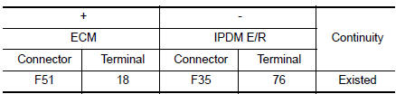
Also check harness for short to ground and to power.
Is the inspection result normal? YES >> GO TO 7.
NO >> Repair or replace error-detected parts.
3.CHECK FUEL PUMP POWER SUPPLY
- Turn ignition switch OFF.
- Disconnect “fuel level sensor unit and fuel pump” harness connector.
- Turn ignition switch ON.
- Check the voltage between “fuel level sensor unit and fuel pump” harness connector and ground.
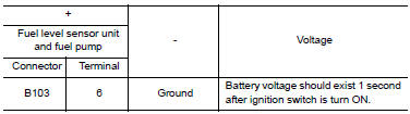
Is the inspection result normal? YES >> GO TO 5.
NO >> GO TO 4.
4.CHECK FUEL PUMP POWER SUPPLY CIRCUIT
- Turn ignition switch OFF.
- Disconnect IPDM E/R harness connector.
- Check the continuity between IPDM E/R harness connector and “fuel level sensor unit and fuel pump” harness connector.
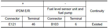
- Also check harness for short to ground and to power.
Is the inspection result normal? YES >> GO TO 7.
NO >> Repair or replace error-detected parts.
5.CHECK FUEL PUMP GROUND CIRCUIT
- Check the continuity between “fuel level sensor unit and fuel pump” and ground.
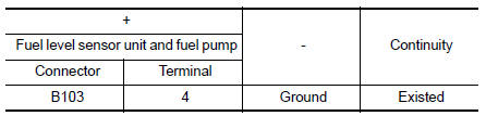
- Also heck harness for short to power.
Is the inspection result normal?
YES >> GO TO 6.
NO >> Repair or replace error-detected parts.
6.CHECK FUEL PUMP
Refer to EC-469, "Component Inspection".
Is the inspection result normal? YES >> GO TO 7.
NO >> Replace “fuel level sensor unit and fuel pump”. Refer to FL-6, "Removal and Installation".
7.CHECK INTERMITTENT INCIDENT
Perform GI-41, "Intermittent Incident".
Is the inspection result normal? YES >> Replace IPDM E/R. Refer to PCS-35, "Removal and Installation".
NO >> Repair or replace harness or connectors.
Component Inspection
1.CHECK FUEL PUMP
- Turn ignition switch OFF.
- Disconnect “fuel level sensor unit and fuel pump” harness connector.
- Check resistance between “fuel level sensor unit and fuel pump” terminals as follows.
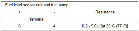
Is the inspection result normal? YES >> INSPECTION END
NO >> Replace “fuel level sensor unit and fuel pump”. Refer to FL-6, "Removal and Installation".
 Fuel injector
Component Function Check
1.INSPECTION START
Turn ignition switch to START.
Are any cylinders ignited?
YES >> GO TO 2.
NO >> Proceed to EC-464, "Diagnosis Procedure".
2. ...
 Ignition signal
Component Function Check
1.INSPECTION START
Turn ignition switch OFF, and restart engine.
Does the engine start?
YES-1 >> With CONSULT: GO TO 2.
YES-2 >> Without CONSULT: GO TO 3. ...
Other materials:
Diagnosis system (BCM) (with intelligent key system)
COMMON ITEM
COMMON ITEM : CONSULT Function (BCM - COMMON ITEM)
APPLICATION ITEM
CONSULT performs the following functions via CAN communication with BCM.
Direct Diagnostic Mode
Description
Ecu Identification
The BCM part number is displayed.
Self Diagnostic ...
Wiring diagram
AUTOMATIC AIR CONDITIONING SYSTEM
Wiring Diagram
...
Power window retained power operation does not operate
properly
Diagnosis Procedure
1.CHECK DOOR SWITCH
Check door switch.
Refer to DLK-149, "Component Function Check" (with Intelligent Key system) or
DLK-319,
"Component Function Check" (without Intelligent Key system).
Is the inspection result normal?
YES >> GO TO 2.
NO ...
