Nissan Rogue Service Manual: Fuel level sensor unit, fuel filter and fuel pump assembly
Exploded View
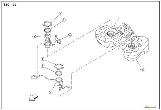
1. Lock ring
2. O-ring
3. Fuel filter and fuel pump assembly
4. Fuel level sensor and fuel tank temperature sensor
5. Lock ring
6. O-ring
7. Sub fuel level sensor assembly
8. Fuel tank
 Fron
Fron
CAUTION: Do not remove or disassemble parts unless instructed as shown.
Removal and Installation
REMOVAL
WARNING: Be sure to read “General Precautions” before working on the fuel system. Refer to FL-2, "General Precaution". Fuel Level Sensor Unit, Fuel Filter And Fuel Pump Assembly
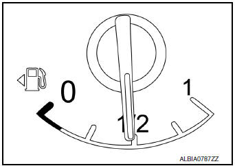
- Check the fuel level with the vehicle on a level surface. If the fuel gauge indicates more than the level as shown (1/2 full), drain the fuel from the fuel tank until the fuel gauge indicates a level at or below as shown (1/2 full).
- In case the fuel pump does not operate, use the following procedure.
- Insert fuel tubing of less than 25mm (0.98in) diameter into the fuel filler tube through the fuel filler opening to drain fuel from the fuel filler tube.
- Disconnect the fuel filler hose from the fuel filler tube.
- Insert fuel tubing into the fuel tank through the fuel filler hose to drain fuel from the fuel tank.
- As a guide, the fuel level reaches or is less than the level on the fuel gauge as shown, when approximately 27.5 (7-1/4 US gal, 6 Imp gal) of fuel is drained from a full fuel tank.
- Release the fuel pressure from the fuel lines. Refer to EC-144, "Work Procedure".
- Open fuel filler lid.
- Open fuel filler cap and release the pressure inside the fuel tank.
- Remove rear seat cushion. Refer to SE-37, "Exploded View".
- Turn the four retainers 90 degrees to disengage the clips and
remove the fuel pump inspection hole cover.
CAUTION: Cover the immeditate area surrounding the fuel pump inspection hole cover with plastic to avoid gasoline damage to carpet.
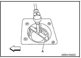
- Disconnect harness connector (A) and quick connector (B).
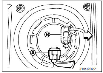
 : Front
Disconnect quick connector as follows:
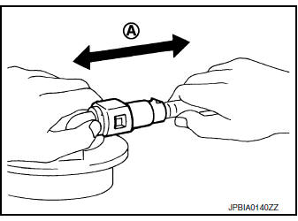
- Hold the sides of connector, press tabs and pull out fuel feed tube.
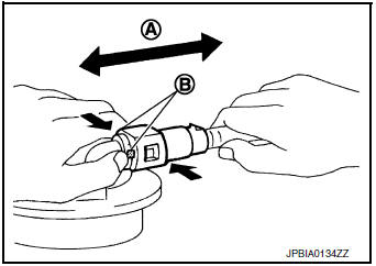
(A) : Pull
(B) : Push in tabs
If quick connector sticks to tube of main fuel level sensor unit, push and pull quick connectors several times until they start to move. Then disconnect them by pulling.
CAUTION:
- Quick connector (1) can be disconnected when the tabs (F) are depressed completely. Do not twist it more than necessary.
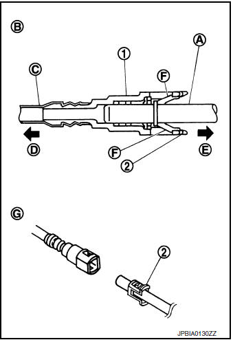
(B) : Connection (cross-section)
(D) : To under floor fuel line
(E) : To fuel tank
(G) : Disconnection
- Do not use any tools to disconnected quick connector.
- Keep resin tube (C) away from heat. Be especially careful when welding near the resin tube.
- Prevent acid liquid such as battery electrolyte, etc. from getting on resin tube.
- Do not bend or twist resin tube during installation and disconnection.
- Do not remove the remaining retainer (2) on hard tube (or the equivalent) (A) except when resin tube or retainer is replaced.
- When resin tube or hard tube (or the equivalent) is replaced, also replace retainer with new one.
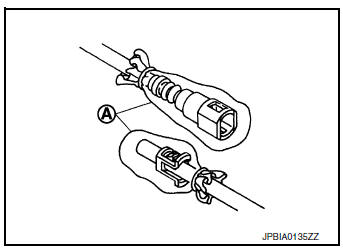
- To keep the connecting portion clean and to avoid damage and foreign materials, cover them completely with plastic bags (A) or something similar.
- Remove the lock ring from the fuel level sensor, fuel filter, and fuel pump assembly.
- Remove the lock ring using Tool (A).
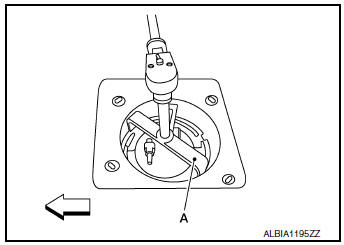
Tool number : ( — ) J-45747 (shown) : KV101207S0 ( — )
: Front
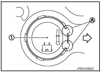
- Prior to removal, observe the alignment between the fuel level sensor, fuel filter, and fuel pump assembly tabs (A) and the matching marks (C) on the fuel tank as shown. This alignment is necessary for proper installation.
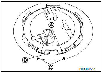
(B) : Retainer mounting pawl
- Raise fuel level sensor unit, fuel filter and fuel pump assembly (1), and disconnect fuel tube and harness connector.
CAUTION:
- Do not bend float arm during removal.
- Do not pollute the inside by residue fuel. Draw out avoiding inclination by supporting with a cloth.
- Do not cause impacts such by dropping when handling components.
Sub Fuel Level Sensor Assembly
- Remove fuel level sensor unit, fuel filter and fuel pump assembly.
- Remove inspection hole cover.
- Using a suitable, remove it by turning clips clockwise by 90 degrees.
- Remove the lock ring from the fuel level sensor, fuel filter, and sub fuel level assembly.
Tool number : ( — ) J-45747 (shown) : KV101207S0 ( — )
: Front
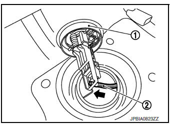
- Remove sub fuel level sensor assembly (1).
CAUTION:
- Do not disassemble a fuel tube (2) from sub fuel sensor assembly.
- Do not bend float arm during removal.
- Do not pollute the inside by residue fuel. Draw out avoiding inclination by supporting with a cloth.
- Do not cause impacts such by dropping when handling components.
NOTE:
Tie a gasoline-resistance rope to a tip of the tube. Draw ( ) and
leave the rope to the fuel tank side so that the rope can be the
guide for installation.
) and
leave the rope to the fuel tank side so that the rope can be the
guide for installation.
INSTALLATION
Installation is in the reverse order of removal.
- Install O-ring to fuel tank without any twist.
CAUTION
Do not reuse O-ring.
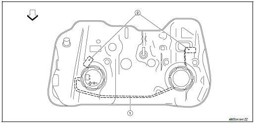
- Using the rope left on the fuel tank side at removal, run the fuel tube inside the fuel tank to install the sub fuel level sensor assembly to the fuel tank.
CAUTION:
- Do not bend float arm during installation.
- To install, fuel tube (1) must run to the front ( ) of the vehicle to avoid the interference with the float arm (2), as shown.
- Align the tabs (A) of the fuel level sensor unit, fuel filter and fuel pump assembly (1) as shown.
: Front
NOTE: Fuel level sensor unit, fuel filter and fuel pump assembly side of fuel tank shown.
- Check the connection for damage or any foreign materials.
- Align the connector with the tube, then insert the connector straight into the tube until a “click” sound is heard.
- After connecting, check that the connection is secured with following procedures.
- Visually confirm that the two tabs are connected to the connector.
- Pull (A) the tube and the connector to check that they are securely connected.
- Before installing inspection hole cover, check that the connecting part has no fuel leaks. Refer to FL-10, "Inspection".
- Install inspection hole covers with the front mark (arrow) facing front.
- Lock clips by turning counterclockwise.
Inspection
INSPECTION AFTER INSTALLATION
Use the following procedure to check for fuel leaks.
- Turn ignition switch “ON” (with engine stopped), then check connections for leaks by applying fuel pressure to fuel piping.
- Start engine. Then let it idle and check that there is no fuel leaks at the fuel system connections.

 Fuel tank
FWD
FWD : Exploded View
Fuel filler cap
Grommet
Fuel filler tube
Cover
Clamp
Fuel filler hose
Clamp
Vent hose
Fuel tank p ...
Other materials:
System
METER SYSTEM
METER SYSTEM : System Description
SYSTEM DIAGRAM
Combination Meter Input Signal (CAN Communication Signal)
DESCRIPTION
Combination Meter
The combination meter controls the following items according to
the signals received from each unit via CAN
communicat ...
Preparation
Special Service Tools
The actual shape of the tools may differ from those illustrated here.
Tool number
(Kent-Moore No.)
Tool name
Description
(J-44321)
Fuel pressure gauge
kit
Checks fuel pressure
KV10120000
Fuel tube adapter
...
ID registration cannot be completed
Description
The ID of the tire pressure sensor installed in each wheel cannot be
registered in the tire pressure monitoring
system. Inspect the tire pressure sensor or the tire pressure monitoring system
circuit.
Diagnosis Procedure
1.CHECK TIRE PRESSURE SENSOR ACTIVATION TOOL
Check tire pr ...
