Nissan Rogue Service Manual: Fuel injector and fuel tube
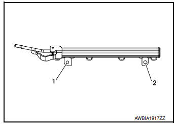
Exploded View
- Rocker cover
- Cylinder head
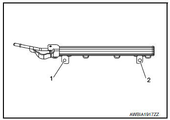
- Fuel tube
- Clip
- O-ring (green)
- Fuel injector
- O-ring (black)
 Front
Front
Removal and Installation
WARNING:
- Put a "CAUTION: FLAMMABLE" sign in the workshop.
- Be sure to work in a well ventilated area and furnish workshop with a CO2 fire extinguisher.
- Do not smoke while servicing fuel system. Keep open flames and sparks away from the work area.
CAUTION:
- Apply new engine oil before installing the parts, as shown above.
- Do not remove or disassemble parts unless instructed as shown.
REMOVAL
- Release the fuel pressure. Refer to EC-144, "Work Procedure".
- Remove intake manifold. Refer to EM-26, "Removal and Installation".
- Remove front exhaust tube and ring gasket. Refer to EX-5, "Exploded View".
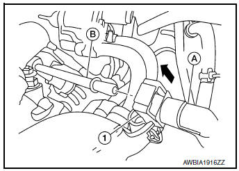
- Disengage red locking clip on quick connector.
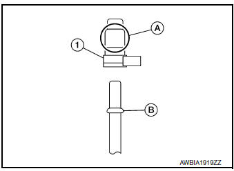
- Disconnect the fuel hose quick connector (1) at the fuel tube side (A).
CAUTION:
- Do not pull with lateral force applied. O-ring inside quick connector may be damaged.
- Prepare container and cloth beforehand as fuel will leak out.
- Avoid fire and sparks.
- Keep parts away from heat source. Especially, be careful when welding is performed around them.
- Do not expose parts to battery electrolyte or other acids.
- Do not bend or twist connection between quick connector and fuel feed tube during installation/ removal.
- To keep the connecting portion clean and to avoid damage and foreign materials, cover them completely with plastic bags or something similar.
- Do not reuse O-ring.
- Disconnect sub-harness for injectors at engine front side, and remove it from bracket.
- Disconnect the fuel injector harness connectors.
- Loosen the bolts in the reverse order shown, then remove fuel tube and fuel injectors as an assembly.
- Remove the fuel injectors from the fuel tube, (if necessary).
- Release the clip.
- Pull fuel injector straight out of the fuel tube.
CAUTION:
- Be careful not to damage the nozzle.
- Avoid any impact, such as dropping the fuel injector.
- Do not disassemble or adjust the fuel injector.
INSTALLATION
- Install new O-rings on the fuel injector.
CAUTION:
- Do not reuse O-rings.
- Upper and lower O-rings are different. Be careful not to confuse them.
Fuel tube side : Black
Nozzle side : Green
- Handle O-rings with bare hands only. Do not wear gloves.
- Lubricate O-rings with new engine oil.
- Do not clean O-rings with solvent.
- Make sure that O-ring and its mating part are free of foreign material.
- Be careful not to scratch O-rings during installation.
- Do not twist or stretch the O-ring. If the O-ring was stretched while it is attached, do not insert it into the fuel tube immediately.
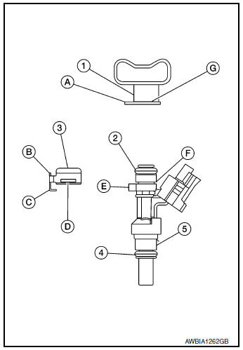
- Install the fuel injector (5) into the fuel tube (1) with the following
procedure:
(2): O-ring (black)
(4): O-ring (green)
- Insert the new clip (3) into the clip groove (F) on fuel injector (5).
- Insert the clip (3) so that protrusion (E) of fuel injector (5) matches cutout (C) of the clip (3).
CAUTION:
- Do not reuse clip (3), replace it with a new one.
- Be careful to keep clip from interfering with O-ring. If interference occurs, replace O-ring.
- Insert fuel injector (5) into fuel tube (1) with clip (3) attached.
- Insert fuel injector (5) so that protrusion (A) of fuel tube (1) matches cut-out (B) of the clip (3).
- Check that fuel tube flange (G) is securely fixed in flange groove (D) on the clip (3).
- Check that installation is complete by checking that fuel injector (5) does not rotate or come off.
- Install fuel tube and fuel injector assembly with the following procedure.
- Insert the tip of each fuel injector into intake manifold.
- Tighten the bolts to specification in the numerical order as shown.
CAUTION: After properly connecting fuel tube assembly to injector and fuel hose, check connection for fuel leaks.
- Connect the fuel hose quick connector.
- Make sure no foreign substances are deposited in and around the fuel tube and quick connector, and there is no damage to them.
- Thinly apply new engine oil around the fuel tube tip end.
- Align center to insert quick connector straight onto fuel tube.
- Insert fuel tube into quick connector (1) until the spool (B) on fuel tube is inserted completely.
- Engage red locking clip on quick connector.
CAUTION:
- Hold at position (A) as shown, when inserting the fuel tube into the quick connector (1).
- Carefully align to center to avoid inclined insertion to prevent damage to the O-ring inside the quick connector (1).
- Insert the fuel tube until you hear a “click” sound and actually feel the engagement.
- To avoid misidentification of engagement with a similar sound.
- Do not reuse O-ring.
- Ensure that red locking clip is firmly secured.
- Installation of the remaining components is in the reverse order of removal.
INSPECTION AFTER INSTALLATION
Make sure there are no fuel leaks at connections as follows:
- Apply fuel pressure to fuel lines by turning ignition switch ON (with engine stopped). Then check for fuel leaks at connections.
- Start the engine and rev it up and check for fuel leaks at connections.
- Perform procedures for “Throttle Valve Closed Position Learning” after finishing repairs. Refer to EC- 140, "Work Procedure".
- If electric throttle control actuator is replaced, perform procedures for “Idle Air Volume Learning” after finishing repairs. Refer to EC-141, "Work Procedure".
WARNING: Do not touch engine immediately after stopping as engine is extremely hot.
NOTE: Use mirrors for checking on connections out of the direct line of sight.
 Rocker cover
Oil filler cap
Rocker cover
Rocker cover gasket
Refer to INSTALLATION
Engine front
Removal and Installation
REMOVAL
Remove intake manifold. Refer to ...
 Timing chain
Exploded View
Cylinder block
Timing chain slack guide
Chain tensioner
Timing chain
Camshaft sprocket (EXH)
Camshaft sprocket (INT)
Oil filte ...
Other materials:
Basic inspection
DIAGNOSIS AND REPAIR WORKFLOW
Work Flow
OVERALL SEQUENCE
DETAILED FLOW
1.GET INFORMATION FOR SYMPTOM
Get detailed information from the customer about the symptom (the
condition and the environment when
the incident/malfunction occurs).
Check operation condition of the ...
P0171 fuel injection system function
DTC Description
DTC DETECTION LOGIC
With the Air/Fuel Mixture Ratio Self-Learning Control, the actual mixture
ratio can be brought closely to the
theoretical mixture ratio based on the mixture ratio feedback signal from the
A/F sensors 1. The ECM calculates
the necessary compensation to corr ...
Condenser
Exploded View
Air guide (LH)
Condenser upper bracket (LH)
Condenser (includes liquid tank)
Condenser upper bracket (RH)
Air guide (RH)
Refrigerant pressure sensor
Condenser lower bracket (RH)
Condenser lower bracket (LH)
CONDENSER
CONDENSER : Removal and In ...
