Nissan Rogue Service Manual: Front passenger air bag module
Exploded View
- Front passenger air bag module
- Steering member
Removal and Installation
WARNING:
- Before servicing the SRS, turn ignition switch OFF, disconnect both battery terminals then wait at least three minutes.
- Always work from the side of air bag module. Do not work in front of it.
- Do not use air tools or electric tools for servicing.
REMOVAL
- Remove the Instrument panel assembly. Refer to IP-14, "INSTRUMENT PANEL ASSEMBLY : Removal and Installation".
- Remove front passenger air bag module screws.
- Release the pawls by removing the front passenger air bag module (1) as shown.
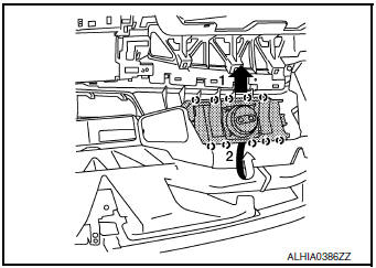
 : Pawl
CAUTION:
- Always place the front passenger air bag module with pad side facing upward as shown.
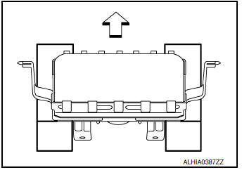
 : Upward
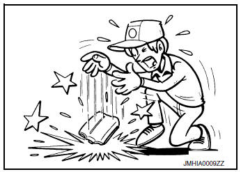
- Replace the front passenger air bag module if it has been dropped or sustained an impact.
- Do not strike the front passenger air bag module.
- Do not insert any foreign objects (screwdriver, etc.) into the passenger air bag module.
- Do not disassemble the passenger air bag module.
- Do not expose the passenger air bag module to temperatures exceeding 90┬░C (194┬░F).
- Do not allow oil, grease, detergent, or water to come in contact with the front passenger air bag module.
INSTALLATION
Note the following items, and then install in the reverse order of removal.
CAUTION:
- Do not reuse the front passenger air bag module bolts.
- Do not damage the front passenger air bag module harness during installation.
- After installation is complete, check that no system malfunction is detected causing the air bag warning lamp to illuminate.
- If a malfunction is indicated by the air bag warning lamp after repair or replacement of the malfunctioning parts, perform the SRS final check. Refer to SRC-18, "Trouble Diagnosis with CONSULT".
 Spiral cable
Exploded View
Combination switch
Steering angle sensor
Spiral cabl
Removal and Installation
WARNING:
Before servicing the SRS, turn ignition switch OFF, disconnect
both ...
 Side curtain air bag module
Exploded View
Side curtain air bag module
Fron
Removal and Installation
WARNING:
Before servicing the SRS, turn ignition switch OFF, disconnect
both battery terminals then ...
Other materials:
Diagnosis system (BCM) (without intelligent key system)
COMMON ITEM
COMMON ITEM : CONSULT Function (BCM - COMMON ITEM)
APPLICATION ITEM
CONSULT performs the following functions via CAN communication with BCM.
Direct Diagnostic Mode
Description
Ecu Identification
The BCM part number is displayed.
Self Diagnostic ...
P0037, P0038 HO2S2 heater
DTC Description
DTC DETECTION LOGIC
DTC No.
CONSULT screen terms
(Trouble diagnosis content)
DTC detecting condition
P0037
HO2S2 HTR (B1)
(HO2S heater control circuit low bank 1
sensor 2)
The current amperage in the heated oxygen sensor 2 heater circuit is
...
Precaution
Precaution for Supplemental Restraint System (SRS) "AIR BAG" and "SEAT
BELT
PRE-TENSIONER"
The Supplemental Restraint System such as ŌĆ£AIR BAGŌĆØ and ŌĆ£SEAT BELT PRE-TENSIONERŌĆØ,
used along
with a front seat belt, helps to reduce the risk or severity of injury to the
...
