Nissan Rogue Service Manual: Exhaust manifold and three way catalyst
Exploded View
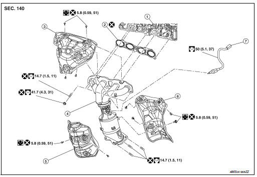
- Cylinder head
- Exhaust manifold and three way catalyst gasket
- Exhaust manifold cover (upper)
- Exhaust manifold and three way catalyst
- Exhaust manifold cover (lower front)
- Exhaust manifold cover (lower rear)
- Air fuel ratio (A/F) sensor 1
Removal and Installation
REMOVAL
- Disconnect battery negative terminal.
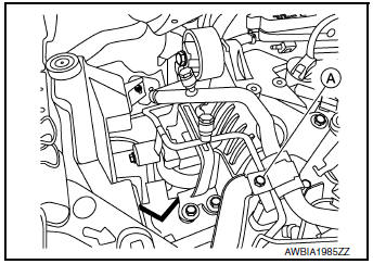
- Remove A/C line bracket bolt (A).
- Remove engine under cover. Refer to EXT-37, "ENGINE UNDER COVER : Removal and Installation".
- Remove the oil level gauge and oil level gauge guide. Refer to EM-92, "Exploded View".
- Remove harness ground wire bolt from generator bracket.
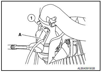
- Disconnect harness connector from air fuel ratio (A/F) sensor 1.
- Remove the air fuel ratio (A/F) sensor 1 (1) using Tool (A), (if necessary).
Tool number : KV10117100 (J-36471-A)
CAUTION:
- Be careful not to damage air fuel ratio (A/F) sensor.
- Discard any air fuel ratio (A/F) sensor which has been dropped from a height of more than 0.5 m (19.7 in) onto a hard surface such as a concrete floor; replace with a new one.
- Detach front exhaust tube from exhaust manifold and three way catalyst. Discard the gasket. Refer to EM-29, "Exploded View".
- Remove the exhaust manifold cover (upper).
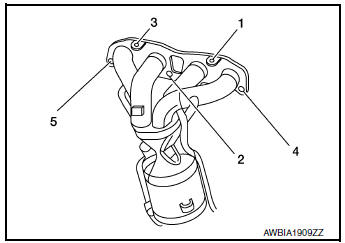
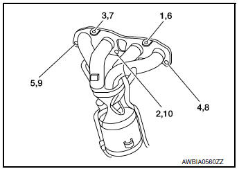
- Loosen the exhaust manifold and three way catalyst nuts in the reverse order as shown.
- Remove exhaust manifold and three way catalyst.
- Remove the exhaust manifold cover (lower front) (if necessary).
- . Remove the exhaust manifold cover (lower rear) (if necessary).
INSPECTION AFTER REMOVAL
Surface Distortion
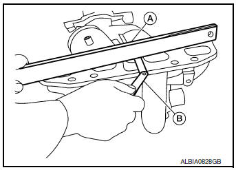
- Check the flatness of exhaust manifold and three way catalyst
using suitable tools (A/B).
NOTE: Place the suitable tool (A) diagonally and measure in several locations.
Limit : 0.3 mm (0.012 in)
INSTALLATION
Exhaust Manifold
Installation is in the reverse order of removal.
CAUTION:
- Do not reuse an exhaust manifold cover which has been dropped.
- Be careful not to deform exhaust manifold covers.
- Install studs in cylinder head studs and exhaust manifold and
three way catalyst (if removed). Then
tighten to specification.
CAUTION: Do not reuse cylinder head or exhaust manifold studs.
- Install the exhaust manifold and exhaust manifold and three way
catalyst gasket. Then tighten the nuts to specification in the
numerical order shown.
CAUTION: Do not reuse exhaust manifold and three way catalyst gasket.
- Install the air fuel ratio (A/F) sensor 1 (1) using Tool (A) and tighten to specification.
Tool number : KV10117100 (J-36471-A)
CAUTION:
- Be careful not to damage air fuel ratio (A/F) sensor.
- Discard any air fuel ratio (A/F) sensor which has been dropped from a height of more than 0.5 m (19.7 in) onto a hard surface such as a concrete floor; replace with a new one.
- Do not over-tighten the air fuel ratio (A/F) sensor 1. Doing so may cause damage to the air fuel ratio (A/F) sensor 1, resulting in a malfunction and the MIL coming on.
 Intake manifold
Exploded View
Intake manifold
Intake manifold gasket
Electirc throttle control actuator O-ring
Electric throttle control actuator
Removal and Installation
REMOVAL ...
 Oil pan and oil strainer
Exploded View
Oil pan, upper
Oil filter
Front cover
O-ring
Oil strainer
Oil pan, lower
Washer
Drain plug
O-ring
Oil level gaug ...
Other materials:
Periodic maintenance
FRONT WHEEL HUB AND KNUCKLE
Inspection
Move the wheel hub and bearing in an axial direction by hand to verify
that looseness of wheel hub and
bearing exists. If any looseness exists, replace the wheel hub and bearing.
Axial end play : Refer to FAX-32, "Wheel Bearing".
Rota ...
Refrigerant
Description
CONNECTION OF SERVICE TOOLS AND EQUIPMENT
Shut-off valve
A/C service valve
Recovery/recycling/recharging
equipment
Refrigerant container (HFC-134a)
Weight scale
Vacuum pump
Manifold gauge set
Preferred (best) method
Alternative method
&n ...
Precaution
Precaution for Supplemental Restraint System (SRS) "AIR BAG" and "SEAT
BELT
PRE-TENSIONER"
The Supplemental Restraint System such as “AIR BAG” and “SEAT BELT PRE-TENSIONER”,
used along
with a front seat belt, helps to reduce the risk or severity of injury to the
...
