Nissan Rogue Service Manual: ECU diagnosis information
ABS ACTUATOR AND ELECTRIC UNIT (CONTROL UNIT)
Reference Value
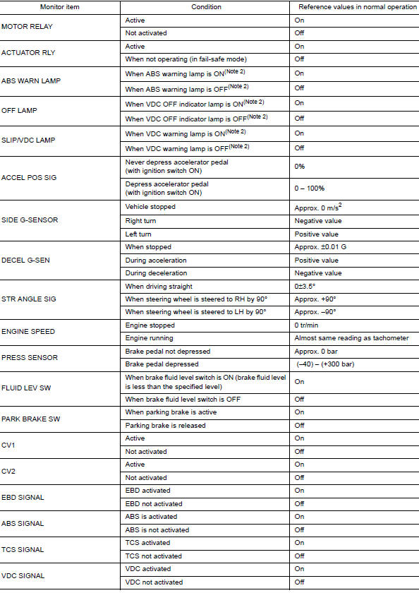
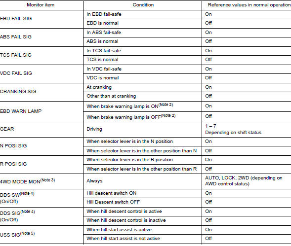
CONSULT DATA MONITOR STANDARD VALUE
NOTE: The following table includes information (items) inapplicable to this vehicle. For information (items) applicable to this vehicle, refer to CONSULT display items.
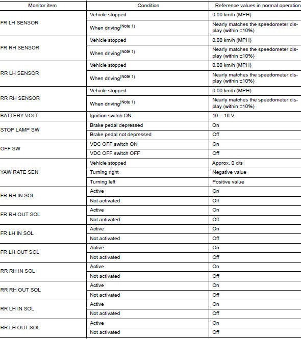
Note 1: Confirm tire pressure is standard value.
Note 2: Refer to BRC-14, "System Description" for ON/OFF conditions of each
warning lamp and indicator
lamp.
Note 3: AWD models
Note 4: DDS (Downhill Drive Support)
Note 5: USS (Hill Start Assist)
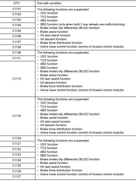
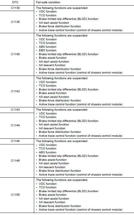
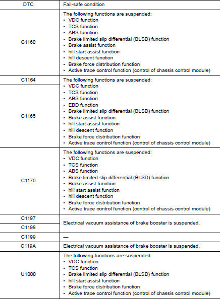
Fail-Safe
VDC FUNCTION, TCS FUNCTION, BRAKE LIMITED SLIP DIFFERENTIAL FUNCTION, BRAKE ASSIST FUNCTION, hill start assist FUNCTION AND BRAKE FORCE DISTRIBUTION FUNCTION
VDC warning lamp in combination meter turn ON when a malfunction occurs in system [ABS actuator and electric unit (control unit)]. The control is suspended for VDC function, TCS function, Brake limited slip differential (BLSD) function, Brake assist function, hill start assist function and Brake force distribution function. The vehicle status becomes the same as models without VDC function, TCS function, Brake limited slip differential (BLSD) function, Brake assist function, hill start assist function and Brake force distribution function. However, ABS function and EBD function are operated normally.
ABS FUNCTION
ABS warning lamp and VDC warning lamp in combination meter turn ON when a malfunction occurs in system [ABS actuator and electric unit (control unit)]. The control is suspended for VDC function, TCS function, ABS function, Brake limited slip differential (BLSD) function, Brake assist function, hill start assist function and Brake force distribution function. The vehicle status becomes the same as models without VDC function, TCS function, ABS function, Brake limited slip differential (BLSD) function, Brake assist function, hill start assist function and Brake force distribution function. However, EBD function is operated normally.
NOTE: ABS self-diagnosis sound may be heard the same as in the normal condition, because self-diagnosis is performed when ignition switch turns ON and when vehicle initially starts.
EBD FUNCTION
ABS warning lamp, brake warning lamp and VDC warning lamp in combination meter turn ON when a malfunction occurs in system [ABS actuator and electric unit (control unit)]. The control is suspended for VDC function, TCS function, ABS function, EBD function, Brake limited slip differential (BLSD) function, Brake assist function, hill start assist function and Brake force distribution function. The vehicle status becomes the same as models without VDC function, TCS function, ABS function, EBD function, Brake limited slip differential (BLSD) function, Brake assist function, hill start assist function and Brake force distribution function.
DTC Inspection Priority Chart
When multiple DTCs are displayed simultaneously, check one by one depending on the following priority list.
|
Priority |
Detected item (DTC) |
| 1 |
|
| 2 |
|
| 3 |
|
| 4 |
|
| 5 |
|
| 6 |
|
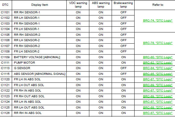
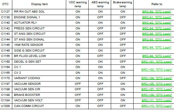
DTC Index
 Diagnosis system [ABS actuator and electric unit (control
unit)]
Diagnosis system [ABS actuator and electric unit (control
unit)]
CONSULT Function
APPLICATION ITEMS
CONSULT can display each diagnostic item using the diagnostic test modes as
follows.
Mode
Function description
ECU identification
...
 Wiring diagram
BRAKE CONTROL SYSTEM
Wiring Diagram
...
Other materials:
CVT position
Inspection
Turn ON the ignition switch with the shift selector at the “P” position.
Press the shift selector button with the brake pedal depressed,
and confirm that the shift selector can be
moved to positions other than “P”. Also confirm that movement is not allowed
from ...
Unit removal and installation
FRONT SUSPENSION MEMBER
Exploded View
Front suspension member
Strut mounting bearing
Rebound stopper insulator
Rebound stopper
Removal and Installation
REMOVAL
Remove the wheel and tire using power tool. Refer to WT-60,
"Removal and Installation&quo ...
Engine compartment check locations
Engine compartment check locations
QR25DE engine
Engine coolant reservoir
Engine oil filler cap
Brake fluid reservoir
Battery
Air cleaner
Fuse/Fusible link box
Radiator cap
Engine oil dipstick
Drive belt location
...
