Nissan Rogue Service Manual: DTC/circuit diagnosis
U1000 CAN COMM CIRCUIT
Description
Refer to LAN-8, "System Description".
DTC Logic
DTC DETECTION LOGIC
|
CONSULT Display |
DTC Detection Condition |
Possible Cause |
| CAN COMM CIRCUIT [U1000] | When IPDM E/R cannot communicate with CAN communication signal continuously for 2 seconds or more. | In CAN communication system, any item (or items) of
the following listed below is malfunctioning:
|
Diagnosis Procedure
1. PERFORM SELF DIAGNOSTIC RESULT
- Turn ignition switch ON and wait for 2 second or more.
- Check “SELF-DIAG RESULTS” of “IPDM E/R”.
Is “CAN COMM CIRCUIT” displayed? YES >> Refer to LAN-17, "Trouble Diagnosis Flow Chart".
NO >> Refer to GI-41, "Intermittent Incident".
B120E IPDM E/R
DTC Logic
DTC DETECTION LOGIC
|
CONSULT Display |
DTC Detection Condition |
Possible Cause |
| USM ECU Not configured [B120E] | The IPDM E/R detects 0V for greater than 2 seconds.
ECU internal failure. |
IPDM E/R |
DTC CONFIRMATION PROCEDURE
1.PERFORM DTC CONFIRMATION
- Turn ignition switch ON.
- Turn ignition switch OFF and wait 1 second or more.
- Turn ignition switch ON.
- Perform “Self Diagnostic Result” of “IPDM E/R” using CONSULT.
Is DTC B120E displayed? YES >> Refer to PCS-32, "Diagnosis Procedure".
NO >> Inspection End.
Diagnosis Procedure
1. PERFORM SELF DIAGNOSTIC RESULT
Perform “Self Diagnostic Result” of “IPDM E/R” using CONSULT.
Is display history of DTC B120E CRNT? YES >> Replace IPDM E/R. Refer to PCS-35, "Removal and Installation".
NO >> Refer to GI-41, "Intermittent Incident".
B20DD IGNITION RELAY ON CIRCUIT
DTC Logic
DTC DETECTION LOGIC
|
CONSULT Display |
DTC Detection Condition |
Possible Cause |
| IGN RELAY ON [B20DD] | The ignition relay ON is detected for 1 second at ignition switch OFF (CPU monitors the status at the contact and excitation coil circuits of the ignition relay inside it | IPDM E/R |
DTC CONFIRMATION PROCEDURE
1.PERFORM DTC CONFIRMATION
- Turn ignition switch ON.
- Turn ignition switch OFF and wait 1 second or more.
- Turn ignition switch ON.
- Perform “Self Diagnostic Result” of “IPDM E/R” using CONSULT.
Is DTC B20DD displayed? YES >> Refer to PCS-32, "Diagnosis Procedure".
NO >> Inspection End.
Diagnosis Procedure
1. PERFORM SELF DIAGNOSTIC RESULT
Perform “Self Diagnostic Result” of “IPDM E/R” using CONSULT.
Is display history of DTC B20DD CRNT? YES >> Replace IPDM E/R. Refer to PCS-35, "Removal and Installation".
NO >> Refer to GI-41, "Intermittent Incident".
B20DE IGNITION RELAY OFF CIRCUIT
DTC Logic
DTC DETECTION LOGIC
|
CONSULT Display |
DTC Detection Condition |
Possible Cause |
| IGN RELAY OFF [B20DE] | The ignition relay OFF is detected for 1 second at ignition switch ON (CPU monitors the status at the contact and excitation coil circuits of the ignition relay inside it). | IPDM E/R |
DTC CONFIRMATION PROCEDURE
1.PERFORM DTC CONFIRMATION
- Turn ignition switch ON.
- Turn ignition switch OFF and wait 1 second or more.
- Turn ignition switch ON.
- Perform “Self Diagnostic Result” of “IPDM E/R” using CONSULT.
Is DTC B20DE displayed? YES >> Refer to PCS-33, "Diagnosis Procedure".
NO >> Inspection End.
Diagnosis Procedure
1. PERFORM SELF DIAGNOSTIC RESULT
Perform “Self Diagnostic Result” of “IPDM E/R” using CONSULT.
Is display history of DTC B20DE CRNT? YES >> Replace IPDM E/R. Refer to PCS-35, "Removal and Installation".
NO >> Refer to GI-41, "Intermittent Incident".
POWER SUPPLY AND GROUND CIRCUIT
Diagnosis Procedure
Regarding Wiring Diagram information, refer to PCS-24, "Wiring Diagram".
1. CHECK FUSE AND FUSIBLE LINKS
Check that the following IPDM E/R fuse or fusible links are not blown.
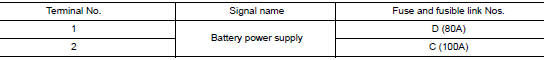
Is the fuse blown? YES >> Replace the blown fuse or fusible link after repairing the affected circuit.
NO >> GO TO 2.
2. CHECK BATTERY POWER SUPPLY CIRCUIT
- Disconnect IPDM E/R connector E118.
- Check voltage between IPDM E/R connector E118 and ground.
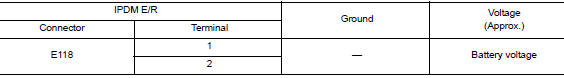
Is the inspection result normal? YES >> GO TO 3.
NO >> Repair or replace harness or connectors.
3. CHECK GROUND CIRCUIT
- Disconnect IPDM E/R connectors E119, E120 and E121.
- Check continuity between IPDM E/R connectors and ground.
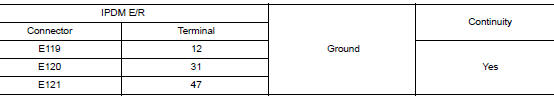
Is the inspection result normal? YES >> Inspection End.
NO >> Repair or replace harness or connectors.
 Wiring diagram
IPDM E/R (INTELLIGENT POWER DISTRIBUTION MODULE ENGINE
ROOM)
Wiring Diagram
...
 Removal and installation
IPDM E/R (INTELLIGENT POWER DISTRIBUTION MODULE ENGINE
ROOM)
Exploded View
IPDM E/R cover
IPDM E/R
IPDM E/R case
IPDM E/R harness cover A
IPDM E/R harness cover B
Front
Remo ...
Other materials:
Steering switch
Description
When one of the steering switches is pushed, the resistance in the steering
switch changes the signal to
identify which button is controlling the information display.
Diagnosis Procedure
Regarding Wiring Diagram information, refer to MWI-32, "Wiring Diagram".
1.CHECK STE ...
AM radio reception
AM signals, because of their low frequency, can
bend around objects and skip along the ground.
In addition, the signals can be bounced off the
ionosphere and bent back to earth. Because of
these characteristics, AM signals are also subject
to interference as they travel from transmitter
to r ...
The parking brake release warning continues displaying,
or does not display
Description
The parking brake warning is displayed during vehicle travel even though
the parking brake is released.
The parking brake warning is not displayed even though driving the
vehicle with the parking brake applied.
Diagnosis Procedure
1.CHECK PARKING BRAKE WARNING LAMP ...
