Nissan Rogue Service Manual: CVT position
Inspection
- Turn ON the ignition switch with the shift selector at the ÔÇťPÔÇŁ position.
- Press the shift selector button with the brake pedal depressed, and confirm that the shift selector can be moved to positions other than ÔÇťPÔÇŁ. Also confirm that movement is not allowed from the ÔÇťPÔÇŁ position to other position without depressing the brake pedal.
- Move the shift selector and check for ÔÇťexcessive effortÔÇŁ, ÔÇťstickingÔÇŁ, ÔÇťnoiseÔÇŁ or ÔÇťrattleÔÇŁ.
- Confirm that shift selector stops at each position with the feel of engagement when it is moved through all the positions. Check whether or not the actual position the shift selector is in matches the position shown by the transaxle body.
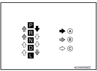
- Make sure that the shift selector is moved to all the shift positions in the manner shown.
- (A): Press shift selector button to operate shift selector, while depressing the brake pedal.
- (B): Press shift selector button to operate shift selector.
- (C): Shift selector can be operated without pressing the shift selector button.
- When the shift selector button is pressed without applying forward/ backward force to the shift selector at ÔÇťPÔÇŁ, ÔÇťRÔÇŁ, ÔÇťNÔÇŁ, ÔÇťDÔÇŁ or "L" positions, there should be no ÔÇťstickingÔÇŁ on the shift selector button operation.
- Check that the back-up lamps do not illuminate when the shift selector is in the ÔÇťPÔÇŁ position.
CAUTION: Check the lighting without pressing shift button.
- Check that the engine can be started with the shift selector in the ÔÇťPÔÇŁ and ÔÇťNÔÇŁ positions only.
- Check that the transaxle is locked completely when the shift selector is in the ÔÇťPÔÇŁ position.
- The relationship between shift selector, engine starting ability, and shift position indicator lighting should satisfy the conditions of the following table.
| Shift selector position | Load direction to the shift selector | Applied load to the shift selector | Engine starting ability | Shift position indicator lighting |
| P | P (over stroke) ÔćÉ P Ôćĺ R | 29.4 N (3.00 kg, 6.61 lb) | Start | P indicator shall be illuminated |
| R | P ÔćÉ R | Not start | R indicator shall be illuminated | |
| N | R ÔćÉ N | ÔÇö | N indicator shall be illuminated | |
| ÔÇö | ÔÇö | Start | ||
| D | ÔÇö | ÔÇö | Not start | D indicator shall be illuminated |
| L | ÔÇö | ÔÇö | Not start | L indicator shall be illuminated |
Adjustment
- Move the selector lever to the ÔÇťPÔÇŁ position.
CAUTION: Rotate the wheels at least a quarter turn and be certain the Park position mechanism is fully engaged.
- Loosen nut (A) and set manual lever (1) to the ÔÇťPÔÇŁ position.
CAUTION: Do not apply force to the manual lever.
- Hold the control cable (2) and push it to direction of the arrow with a specified force.
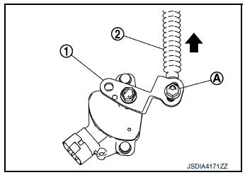
Specified force : 9.8 N (1.0 kg, 2.2 lb)
- Temporarily tighten the nut with the control cable loose.
- Tighten the nut to the specified torque. Refer to TM-197, "Exploded View".
CAUTION: Hold the manual lever securely in the "P" position when tightening control cable nut.
How to erase permanent DTC
Description
Permanent DTC can be erased by driving each driving pattern.
ECM recognizes each driving pattern; it transmits signals to each control module when the driving is complete.
Each control module erases permanent DTC based on those signals. For details, refer to EC-151, "Description".
 Stall test
Work Procedure
INSPECTION
Check the engine oil level. Replenish if necessary. Refer to LU-7,
"Inspection".
Check for leak of the CVT fluid. Refer to TM-190, "Inspe ...

Other materials:
U0101 CAN comm circuit
Description
CAN (Controller Area Network) is a serial communication line for real time
application. It is an on-vehicle multiplex
communication line with high data communication speed and excellent error
detection ability. Many electronic
control units are equipped onto a vehicle, and each co ...
B0098 front door satellite sensor RH
DTC Logic
DTC DETECTION LOGIC
With CONSULT
CONSULT name
DTC
DTC detecting condition
Repair order
DOOR SATELLITE SENSOR RH
[SENSOR FAIL]
B0098
Front door satellite sensor RH has malfunctioned.
Refer to SRC-72, "Diagnosis Procedure".
...
Unit removal and installation
ENGINE ASSEMBLY
Exploded view
Engine mounting insulator (RH)
Upper torque rod (RH)
Engine mounting bracket (RH)
Lower torque rod
Torque rod bracket
Engine mounting insulator (LH)
Removal and installation (FWD)
WARNING:
Situate the vehicl ...
