Nissan Rogue Service Manual: Cowl top
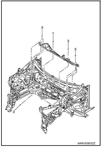
Exploded View
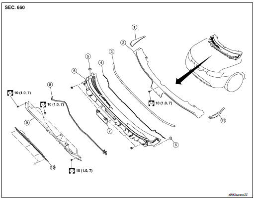
- Cowl top side trim cover (RH)
- Cowl top cover screen
- Cowl top cover seal
- EPT seal
- Cowl top cover plug
- Cowl top cover
- Cowl top cover mask
- Cowl top extension seal
- Cowl top extension
- Cowl top insulation
- Cowl top side trim cover (LH)
Removal and Installation
COWL TOP COVER
Removal
- Remove front wiper arms (LH/RH). Refer to WW-63, "Removal and Installation".
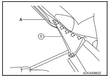
- Release pawls using suitable tool (A) and remove cowl top side
trim cover (1) (LH/RH).
 : Pawl
- Disconnect front washer tube connector.
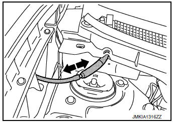
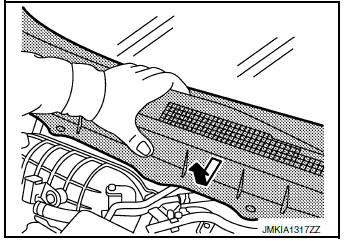
- Remove cowl top cover clips, then pull forward to release cowl top cover and remove.
CAUTION: When performing the procedure after removing cowl top cover, cover the lower end of windshield glass with urethane etc.
- Remove the following parts after removing cowl top cover (if necessary).
- Cowl top seal
- Cowl top cover plug
- Washer nozzle, Refer to WW-60, "Removal and Installation - Front Washer Nozzle".
- Washer tube,WW-60, "Removal and Installation - Front Washer Nozzle".
- EPT sealer
Installation
Installation is in the reverse order of removal.
CAUTION: When installing cowl top cover, check that clips are securely fitted in body panel holes and then press them in.
COWL TOP EXTENSION
Removal
- Remove the front wiper drive assembly. Refer to WW-66, "Removal and Installation".
- Remove the cowl top extension bolts and the cowl top extension.
INSTALLATION
Installation is in the reverse order of removal.
CAUTION: When installing cowl top cover, check that clips are securely placed in panel holes on body and then pressed in.
NOTE: When installing the cowl top extension, tighten the bolts to specification in the order shown.
 Front grille
Exploded View
Front bumper fascia
Front camera (if equipped)
Front grille
Front emblem
Pawl
Clip
Removal and Installation
REMOVAL
Remove front grille upper clip (A) ...
 Fender protector
FENDER PROTECTOR
FENDER PROTECTOR : Exploded View
Front fender protector
Engine side cover
Front fender
Over fender
Clip
Front
FENDER PROTECTOR : Removal and Installation
RE ...
Other materials:
B0028 side airbag module RH
Description
DTC B0028 FRONT RH SIDE AIR BAG MODULE
The front RH side air bag module is wired to the air bag diagnosis sensor
unit. The air bag diagnosis sensor
unit will monitor for opens and shorts in detected lines to the front RH side
air bag module.
PART LOCATION
Refer to SRC-6, "C ...
DTC/circuit diagnosis
U1000 CAN COMM CIRCUIT
Description
Refer to LAN-8, "System Description".
DTC Logic
DTC DETECTION LOGIC
CONSULT Display
DTC Detection Condition
Possible Cause
CAN COMM CIRCUIT
[U1000]
When IPDM E/R cannot communicate with CAN communication
sig ...
ECU diagnosis information
EPS CONTROL UNIT
Reference Value
VALUES ON THE DIAGNOSIS TOOL
CAUTION:
The output signal indicates the EPS control unit calculation data. The normal
values will be displayed
even in the event that the output circuit (harness) is open.
NOTE:
The following table includes information (items) ...
