Nissan Rogue Service Manual: Cooler pipe and hose
Exploded View
- Condenser
- High-pressure flexible hose
- Low-pressure flexible hose
- Low-pressure pipe
- Heating and cooling unit assembly
- High-pressure pipe
- Compressor
- O-ring
- Low-pressure service port
- High-pressure service port
LOW-PRESSURE PIP
LOW-PRESSURE PIPE : Removal and Installation
REMOVAL
- Discharge the refrigerant. Refer to HA-23, "Recycle Refrigerant".
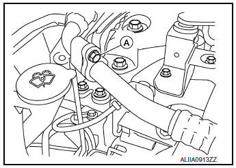
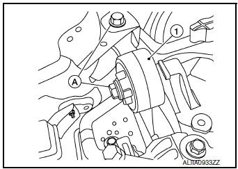
- Remove bolts (A) and engine upper mount (1).
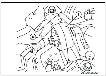
- Remove the bolt (A) that retains the low-pressure flexible hose to the low-pressure pipe.
CAUTION: Cap or wrap the joint of the pipe with suitable material such as vinyl tape to avoid the entry of air.
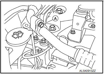
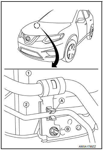
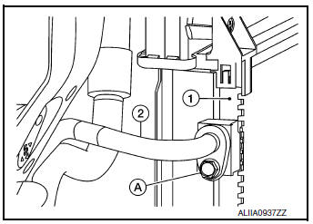
- Remove low-pressure pipe bracket bolts (A) and bracket.
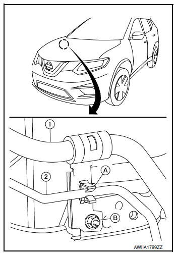
- Release high-pressure pipe (2) from clamp (A).
- Remove nut (B) and low-pressure pipe (1).
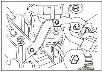
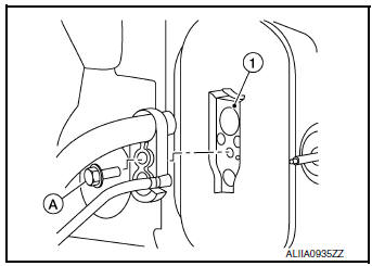
- Remove the bolt (A) that retains the low-pressure and high-pressure pipe to the expansion valve (1).
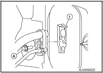
- Remove low-pressure pipe.
INSTALLATION
Installation is in the reverse order of removal.
CAUTION:
- Tighten bolts to specified torque. Refer to HA-32, "Exploded View".
- Do not reuse O-rings.
- Apply A/C oil to new O-rings for installation.
- After charging refrigerant, check for leaks. Refer to HA-21, "Leak Test".
LOW-PRESSURE FLEXIBLE HOSE
LOW-PRESSURE FLEXIBLE HOSE : Removal and Installation
REMOVAL
- Discharge the refrigerant. Refer to HA-23, "Recycle Refrigerant".
- Remove the bolt (A) that retains the low-pressure flexible hose to the low-pressure pipe.
CAUTION: Cap or wrap the joint of the pipe with suitable material such as vinyl tape to avoid the entry of air.
- Remove the nut (A) that retains the low-pressure flexible hose to the compressor.
- Remove the low-pressure flexible hose.
INSTALLATION
Installation is in the reverse order of removal.
CAUTION:
- Tighten nut/bolt to specified torque. Refer to HA-32, "Exploded View".
- Do not reuse O-rings.
- Apply A/C oil to new O-rings for installation.
- After charging refrigerant, check for leaks. Refer to HA-21, "Leak Test".
HIGH-PRESSURE PIPE
HIGH-PRESSURE PIPE : Removal and Installation
REMOVAL
- Discharge the refrigerant. Refer to HA-23, "Recycle Refrigerant".
- Remove front bumper fascia. Refer to EXT-17, "Removal and Installation".
- Remove air duct assembly. Refer to EM-24, "Exploded View".
- Remove bolts (A) and upper engine mount (1).
- Release high-pressure pipe (2) from clamp (A).
(1): Low-pressure pipe
(B): Nut
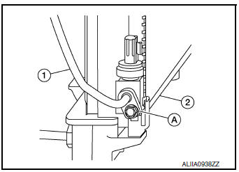
- Remove bolt (A) that retains high-pressure pipe (1) to the condenser
(2).
CAUTION: Cap or wrap the joint of the pipe with suitable material such as vinyl tape to avoid the entry of air.
- Remove the bolt (A) that retains the high-pressure and low-pressure pipe to the expansion valve (1).
- Remove high-pressure pipe.
INSTALLATION
Installation is in the reverse order of removal.
CAUTION:
- Tighten bolts to specified torque. Refer to HA-32, "Exploded View".
- Do not reuse O-rings.
- Apply A/C oil to new O-rings for installation.
- After charging the refrigerant, check for leaks. Refer to HA-21, "Leak Test".
HIGH-PRESSURE FLEXIBLE HOSE
HIGH-PRESSURE FLEXIBLE HOSE : Removal and Installation
REMOVAL
- Discharge the refrigerant. Refer to HA-23, "Recycle Refrigerant".
- Remove front bumper fascia. Refer to EXT-17, "Removal and Installation".
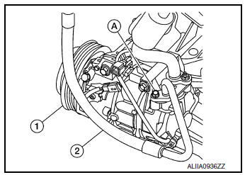
- Remove the bolt (A) that retains the high-pressure flexible hose (2) to the condenser (1).
CAUTION: Cap or wrap the joint of the pipe with suitable material such as vinyl tape to avoid the entry of air.
- Remove the bolt (A) that retains the high-pressure flexible hose (2) to the compressor (1).
INSTALLATION
Installation is in the reverse order of removal.
CAUTION:
- Tighten bolts to specified torque. Refer to HA-37, "Exploded View".
- Do not reuse O-rings.
- Apply A/C oil to new O-rings for installation.
- After charging the refrigerant, check for leaks. Refer to HA-21, "Leak Test".
 Compressor
Exploded View
Compressor
Removal and Installation
REMOVAL
Discharge the refrigerant. Refer to HA-23, "Recycle Refrigerant".
Remove the engine under cover. Refer to EX ...
 Condenser
Exploded View
Air guide (LH)
Condenser upper bracket (LH)
Condenser (includes liquid tank)
Condenser upper bracket (RH)
Air guide (RH)
Refrigerant pressure sensor
C ...
Other materials:
The ambient temperature display is incorrect
Description
The displayed outside air temperature is higher than the actual
temperature.
The displayed outside air temperature is lower than the actual
temperature.
Outside air temperature is not indicated.
Diagnosis Procedure
1.CHECK AMBIENT SENSOR SIGNAL CIRCUIT
Chec ...
P2122, P2123 APP sensor
DTC Description
DTC DETECTION LOGIC
DTC No.
CONSULT screen terms
(Trouble diagnosis content)
DTC detecting condition
P2122
APP SEN 1/CIRC
(Throttle/pedal position sensor/switch ″D″
circuit low)
An excessively low voltage from the APP sensor 1 is sen ...
Wiring diagram
POWER DOOR LOCK SYSTEM
Wiring Diagram
REMOTE KEYLESS ENTRY SYSTEM
Wiring Diagram
...
