Nissan Rogue Owners Manual: Connecting Procedure
Connecting Procedure
NOTE: The connecting procedure must be performed when the vehicle is stationary. If the vehicle starts moving during the procedure, the procedure will be cancelled.
- Press the [
 ] button
on the control
panel.
] button
on the control
panel. - Touch the ÔÇťSettingsÔÇŁ key.
- Touch the ÔÇťPhone & BluetoothÔÇŁ key.
- Touch the ÔÇťConnect New DeviceÔÇŁ key.
- Initiate the connecting process from the handset. The system will display the message: ÔÇťIs PIN XXXXXX displayed on your Bluetooth device?ÔÇŁ. If the PIN is displayed on your Bluetooth┬« device, select ÔÇťYesÔÇŁ to complete the pairing process.
For additional information, refer to the Bluetooth┬« deviceÔÇÖs OwnerÔÇÖs Manual.
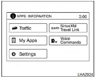
 Voice commands
You can use voice commands to operate various
Bluetooth® Hands-Free Phone System features
using the NISSAN Voice Recognition system. For
additional information, refer to ÔÇťNISSAN Voice
Recogniti ...
 Vehicle phonebook
To access the vehicle phonebook:
Press the button on
the control panel.
Touch the ÔÇťPhonebookÔÇŁ key.
Choose the desired entry from the displayed
list.
The num ...
Other materials:
Precaution
Precaution for Supplemental Restraint System (SRS) "AIR BAG" and "SEAT
BELT
PRE-TENSIONER"
The Supplemental Restraint System such as ÔÇťAIR BAGÔÇŁ and ÔÇťSEAT BELT PRE-TENSIONERÔÇŁ,
used along
with a front seat belt, helps to reduce the risk or severity of injury to the
...
Active engine brake
The Active Engine Brake function adds subtle
deceleration by controlling CVT gear ratio, depending
on the cornering condition calculated
from driverÔÇÖs steering input and plural sensors.
This benefit is for easier traceability and less
workload of adjusting speed with braking at corners.
...
Tire labeling
Example
Federal law requires tire manufacturers to
place standardized information on the
sidewall of all tires. This information identifies
and describes the fundamental
characteristics of the tire and also provides
the tire identification number (TIN)
for safety standard certification. The ...
