Nissan Rogue Service Manual: Condenser
Exploded View
- Air guide (LH)
- Condenser upper bracket (LH)
- Condenser (includes liquid tank)
- Condenser upper bracket (RH)
- Air guide (RH)
- Refrigerant pressure sensor
- Condenser lower bracket (RH)
- Condenser lower bracket (LH)
CONDENSER
CONDENSER : Removal and Installation
REMOVAL
CAUTION: Before servicing, turn the ignition switch off, disconnect both battery cables and wait at least three minutes.
- Disconnect the negative and positive battle terminals and wait at least three minutes. Refer to PG-75, "Removal and Installation (Battery)".
- Discharge the refrigerant. Refer to HA-23, "Recycle Refrigerant".
- Remove front air duct. Refer to EM-24, "Removal and Installation".
- Remove front bumper fascia. Refer to EXT-17, "Removal and Installation".
- Remove front combination lamp (RH). Refer to EXL-119, "Removal and Installation".
- Remove air guides (LH/RH). Refer to HA-37, "Exploded View".
- Remove crash zone sensor. Refer to SR-22, "Removal and Installation".
- Disconnect the harness connector from the refrigerant pressure sensor.
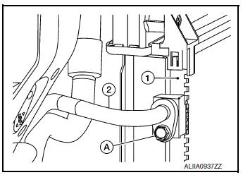
- Remove the bolt (A) that retains the high-pressure flexible hose (2) to the condenser (1).
CAUTION: Cap or wrap the joint of the pipe with suitable material such as vinyl tape to avoid the entry of air.
- Remove bolt (A) that retains high-pressure pipe (1) to condenser (2).
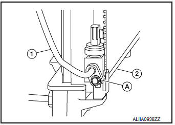
- Remove the condenser bracket bolts and condenser.
INSTALLATION
Installation is in the reverse order of removal.
CAUTION:
- Tighten bolts to specification. Refer to HA-32, "Exploded View".
- Do not reuse O-rings.
- Apply A/C oil to new O-rings for installation.
- After charging the refrigerant, check for leaks. Refer to HA-21, "Leak Test".
LIQUID TANK
LIQUID TANK : Removal and Installation
The liquid tank is serviced as an assembly with the condenser. Refer to HA-37, "CONDENSER : Removal and Installation".
REFRIGERANT PRESSURE SENSOR
REFRIGERANT PRESSURE SENSOR : Removal and Installation
REMOVAL
- Discharge the refrigerant. Refer to HA-23, "Recycle Refrigerant".
- Remove front air duct. Refer to EM-24, "Removal and Installation".
- Remove front bumper fascia. Refer to EXT-17, "Removal and Installation".
- Remove air guide (RH). Refer to HA-37, "Exploded View".
- Disconnect the harness connector from the refrigerant pressure sensor and remove.
CAUTION: Cap or wrap the opening of the refrigerant pressure sensor with suitable material such as vinyl tape to avoid the entry of air.
INSTALLATION
Installation is in the reverse order of removal.
CAUTION:
- Do not reuse O-ring.
- Apply A/C oil to new O-rings for installation.
- After charging the refrigerant, check for leaks. Refer to HA-21, "Leak Test".
 Cooler pipe and hose
Exploded View
Condenser
High-pressure flexible hose
Low-pressure flexible hose
Low-pressure pipe
Heating and cooling unit assembly
High-pressure pipe
Compressor
...
 Heating and cooling unit assembly
Exploded View
Steering Member
Heating and cooling unit assembly
Steering member
Bolt
Nut
Automatic Air Conditioning
Wiring harness
Air mix door duct (LH)
...
Other materials:
Preparation
Special Service Tool
The actual shape of the tool may differ from those illustrated here.
Tool number
(TechMate No.)
Tool name
Description
KV991J0080
(J-45741)
ABS active wheel sensor tester
Checking operation of ABS active wheel sensors
Comm ...
Wiring diagram
MANUAL AIR CONDITIONING SYSTEM
Wiring Diagram
...
CVT oil warmer
Exploded View
Transaxle assembly
CVT oil warmer
: N·m (kg-m, in-lb)
Removal and Installation
REMOVAL
WARNING:
Do not remove the radiator cap when the engine is hot. Serious burns could occur
from high pressure
engine coolant escaping from the radiator. Wrap a thick cloth around ...
