Nissan Rogue Service Manual: Component parts
Component Parts Location
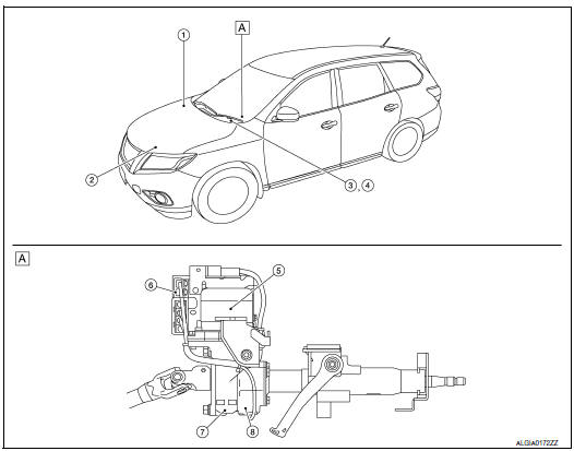
- Steering column assembly
| No. | Component | Function |
| 1 | ABS actuator and electric unit (control unit) |
|
| 2 | ECM |
|
| 3 | Combination meter |
|
|
||
| 4 | EPS warning lamp | STC-7, "EPS SYSTEM : System Description" |
| 5 | EPS motor | STC-6, "EPS Motor, Torque Sensor, Reduction Gear" |
| 6 | EPS control unit | STC-6, "EPS Control Unit" |
| 7 | Reduction gear | STC-6, "EPS Motor, Torque Sensor, Reduction Gear" |
| 8 | Torque sensor | STC-6, "EPS Motor, Torque Sensor, Reduction Gear" |
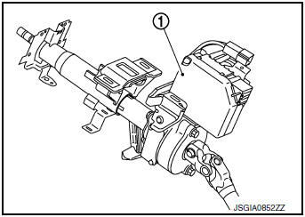
EPS Control Unit
- EPS control unit (1) is installed to steering column assembly.
- EPS control unit performs an arithmetical operation on data, such as steering wheel turning force (sensor signal) from the torque sensor, vehicle speed signal, etc. Then it generates an optimum assist torque signal to the EPS motor according to the driving condition.
- EPS control unit decreases the output signal to EPS motor during continuous extreme use of the power steering function (e.g., full steering) for protection of the EPS motor and EPS control unit (Overload protection control).
EPS Motor, Torque Sensor, Reduction Gear
EPS motor (1), torque sensor (2) and reduction gear (3) are installed to steering column assembly.
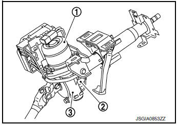
EPS MOTOR
EPS motor provides assist torque in proportion to the control signal from the EPS control unit.
TORQUE SENSOR
Torque sensor detects the steering torque and transmits the signal to the EPS control unit.
REDUCTION GEAR
Reduction gear increases the assist torque provided from the EPS motor, and outputs to the column shaft.

 System
EPS SYSTEM
EPS SYSTEM : System Description
SYSTEM DIAGRAM
INPUT/OUTPUT SIGNAL
Communicates the signal from each control unit via CAN communication.
Control unit
Signal statu ...
Other materials:
Unit removal and installation
FRONT SUSPENSION MEMBER
Exploded View
Front suspension member
Strut mounting bearing
Rebound stopper insulator
Rebound stopper
Removal and Installation
REMOVAL
Remove the wheel and tire using power tool. Refer to WT-60,
"Removal and Installation&quo ...
Brake pedal
Adjustment
BRAKE PEDAL HEIGHT
Remove instrument lower panel LH. Refer to IP-22, "Removal and
Installation".
Disconnect the harness connectors from the stop lamp switch and
brake pedal position switch.
Turn the stop lamp switch and brake pedal position switc ...
Symptom diagnosis
THE SPORT MODE INDICATOR LAMP DOES NOT TURN ON
Description
The SPORT mode indicator lamp does not turn ON when the SPORT mode switch is
operated.
Diagnosis Procedure
1.CHECK SPORT MODE INDICATOR LAMP FUNCTION
Perform combination meter self-diagnosis mode and check test order 10. Refer
to MW ...
