Nissan Rogue Service Manual: Component parts
Component Parts Location
|
No. |
Component |
Function |
| 1 | Key switch | Transmits the key switch signal to the BCM.
Refer to SEC-115, "Component Parts Location" (without Intelligent Key system) for detailed installation location. |
| 2 | Combination meter |
|
| 3 | ABS actuator and electric unit (control unit) | Transmits the vehicle speed signal to the combination meter via CAN
communication.
Refer to BRC-8, "Component Parts Location" for detailed installation location. |
| 4 | Parking brake switch | Transmits the parking brake switch signal to the combination meter. |
| 5 | BCM | Based on the signals received from various units and switches,
transmits the buzzer output signal
to the combination meter via CAN communication.
Refer to BCS-7, "BODY CONTROL SYSTEM : Component Parts Location" (with Intelligent Key system) or BCS-79, "BODY CONTROL SYSTEM : Component Parts Location" (without Intelligent Key system) for detailed installation location. |
| 6 | Seat belt buckle switch LH | Transmits a seat belt buckle switch signal LH to the combination meter. |
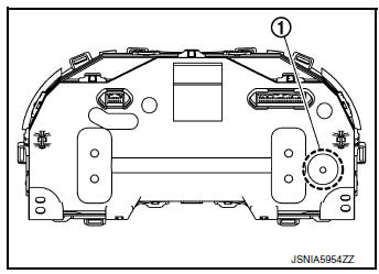
Combination Meter
The combination meter has a built-in buzzer (1) and sounds the following warnings, according to signals from each switch and unit:
- Light reminder warning
- Parking brake release warning chime
- Seat belt warning
- Key warning chime

 System
WARNING CHIME SYSTEM
WARNING CHIME SYSTEM : System Description
SYSTEM DIAGRAM (WITH INTELLIGENT KEY SYSTEM)
SYSTEM DIAGRAM (WITHOUT INTELLIGENT KEY SYSTEM)
COMBINATION METER INPUT/OUTPUT S ...
Other materials:
Operating the power liftgate (if so equipped)
WARNING
Make sure that all passengers have
their hands, etc., inside the vehicle before
closing the liftgate.
Do not leave children unattended inside
the vehicle. They could unknowingly activate
switches or controls. Unattended
children could become inv ...
Engine compartment check locations
QR25DE engine
Engine coolant reservoir
Engine oil filler cap
Brake fluid reservoir
Battery
Air cleaner
Fuse/Fusible link box
Radiator cap
Engine oil dipstick
Drive belt location
Windshield-washer fluid reservoir ...
Precaution
Precaution for Supplemental Restraint System (SRS) "AIR BAG" and "SEAT
BELT
PRE-TENSIONER"
The Supplemental Restraint System such as ŌĆ£AIR BAGŌĆØ and ŌĆ£SEAT BELT
PRE-TENSIONERŌĆØ, used along
with a front seat belt, helps to reduce the risk or severity of injury to the
...
